RISC-V ALE Exercise Book
Complementary exercises for An Introduction to Assembly Programming with RISC-V textbook
Contributors:
- João Seródio
- Edson Borin
Introduction
This book contains a set of exercises to support professors and students in the assembly language learning process. The book is organized in chapters. Each chapter assumes the student has already learned a given set of concepts covered by the textbook (An Introduction to Assembly Programming with RISC-V).
Getting Started
This chapter contains a set of exercises to help students getting started with code generation tools, including the compiler, the assembler, the linker and the disassembler tools.
Step-by-step compilation process
This exercise is a tutorial that guides the student to generate executable files from source files. It requires the students to perform, step-by-step, all the code generation steps, including compilation, assembling, and linking.
Instructions
Perform the following program compilation process step-by-step, i.e., generating the assembly language code and then the object code for each source file and finally calling the linker to put all the object files together and produce the executable file named prog.x. You must use the clang-15 compiler and generate code for the RISC-V R32 architecture.
The program is composed of two source files: file1.c and file2.c. The following listings show the file contents.
extern void write(int __fd, const void *__buf, int __n);

int main(void) {
  const char str[] = "Hello World!\n";
  write(1, str, 13);
  return 0;
}
extern int main(void);

void exit(int code) {
  __asm__ __volatile__(
    "mv a0, %0           # return code\n"
    "li a7, 93           # syscall exit (93) \n"
    "ecall"
    :             // Output list
    :"r"(code)    // Input list
    : "a0", "a7"
  );
}

void write(int __fd, const void *__buf, int __n){
  __asm__ __volatile__(
    "mv a0, %0           # file descriptor\n"
    "mv a1, %1           # buffer \n"
    "mv a2, %2           # size \n"
    "li a7, 64           # syscall write (64) \n"
    "ecall"
    :   // Output list
    :"r"(__fd), "r"(__buf), "r"(__n)    // Input list
    : "a0", "a1", "a2", "a7"
  );
}

void _start() {
  int ret_code = main();
  exit(ret_code);
}
To perform this task, you must, first, create these two files (with their respective contents) on your computer.
Once the compilation is complete, you must:
- Use the disassembler tool to inspect the contents of the object and executable files. You'll notice that it contains the sequence of instructions listed in the function write from file2.c and the names of functions main, _start, and write.
- Compare the contents of file1.s assembly file with the output generated by the disassembling tool for the file1.o file.
Notes and Tips
- Remember to use the RISC-V 32 compilation tools, otherwise you might not be able to correctly compile file2.c (Notice that this file contains assembly instructions for RISC-V processors).
Automating the compilation process with Makefiles
This exercise requires students to reason about the compilation process and automate this process with Makefiles.
Instructions
In this exercise, you must produce a Makefile script that automates the compilation process carried out manually in the previous exercise, i.e., for a program that contains two source files (file1.c and file2.c). The final file to be produced must be named prog.x. For this, you must create a rule for each intermediate file, until you reach the final file.
You might test your script executing the following commands:
make file1.s
make file2.s
make file1.o
make file2.o
make prog.x
These commands must generate, respectively: the assembly code for file1.c and file2.c; the object files file1.o and file2.o; and, finally, the executable file named prog.x.
Notes and Tips
- This link provides information about make and Makefiles.
Getting Started with the Simulator
This chapter contains a set of exercises to help students getting started with the ALE simulator.
All exercises in this chapter assume the student is already familiar with compiling, assembling, and linking code for RISC-V processors, covered by the exercises of the previous chapter.
Running the Hello World program
This exercise is a tutorial that guides the student to run executable files on the simulator.
Prerequisites
- Complete exercise 1.1 to generate the Hello World program (prog.x).
ALE Simulator Tutorial
The RISC-V ALE is a simulator that runs on your browser and can be accessed at ALE Simulator.
Loading files
The simulator has its own file system that enables storing multiple files. To load files, you need to click on the file button at the top right corner (left of RUN button), and select the files that you wish to load from your computer.
You can load executable files, source files or even data files to be accessed by your programs.
There is no directory structure and existing files with the same name are automatically overwritten, in other words, if you load a file named prog.x more than once, just the last one will be kept.
Running
Once you have loaded your files, you can start your program execution. To do so, you must click on the RUN button (top right corner).
The simulator will identify the source files and, if necessary, perform the compiling, assembling and linking to get the executable.
Note that for this case, if the C files are loaded, a warning is issued during the compilation process (function declared 'noreturn' should not return) due to the exit function definition.
This warning can be ignored.
Finally, the simulator will invoke the executable and show the program's output (if there is any).
Note: The simulator stops the program's execution when (i) the program invokes the system call (syscall) exit, or (ii) when the execution finds invalid instructions. In the last case, the simulator may show error messages like "Error: Failed stop: 64 consecutive illegal instructions: 0". This is expected in programs that do not call the exit syscall, as the processor doesn't know where the program ends and will continue to execute instructions consecutively, until it finds invalid instructions.
Instructions
Load and execute the prog.x file on the ALE simulator and inspect the output produced by the program on the simulator terminal. You should see the string "Hello world!".
Using the Assistant to check a Simple Symbol Calculator program
This exercise is a simple program that must be executed on the ALE Simulator and checked using the Assistant's tests.
Development Tutorial
Programs written in C are usually linked to the C standard library and with object files that contain support routines to the application's execution. These routines, initialize the C library's data structures, organize the parameters to the main function (_start) and, after returning from the main function, invoke the operating system to signal the end of the application (function exit).
_start function and exit syscall
Besides linking the code from multiple object files (.o), the linker must register the address of the entry function of the program on the header of the executable file so that the operating system's loader knows where to start the execution of the program once it starts. By default, in C and C++, the program's entry point is defined by the function called _start. This is a short function that invokes the function main() and after main returns, it invokes the exit syscall. to inform the operating system that the program has finished.
When generating the executable files, C and C++ compilers link an object file that has the implementation of this function. However, the RISC-V compiler used here doesn't link to such file (nor LibC), this way, it is necessary to include an implementation of the function.
The following code shows possible implementations to the function exit and the function _start. In this example, the function exit consists of a sequence of instructions in assembly language that copies the value of function parameter (code) to the register a0, puts the value 93 on register a7 and generates a software interrupt (ecall instruction). The software interrupt redirects the execution flow to the operating system, which will use the value on register a7 to determine which syscall was requested and the value on register a0 as a parameter to the call.
void exit(int code)
{
  __asm__ __volatile__(
    "mv a0, %0           # return code\n"
    "li a7, 93           # syscall exit (93) \n"
    "ecall"
    :             // Output list
    :"r"(code)    // Input list
    : "a0", "a7"
  );
}

void _start()
{
  int ret_code = main();
  exit(ret_code);
}
The _start function code simply calls the main function, which is implemented by the user, and, after main's return, invokes the exit function passing the main return value as a parameter.
You can copy and paste these two functions on your C programs that will be executed on the ALE simulator. Alternatively, you can put them in a file called start.c and compile/assemble/link the file with your program.
read and write syscalls
In general, programs that execute in computer systems that have an operating system don't have direct access to the system's peripherals (e.g., monitor, keyboard, mouse, ...), in other words, that can't interact directly with these devices. In this case, all interactions with these devices are done via system calls (syscalls).
The organization of the Linux operating system is strongly based on the concept of files. In this context, each file is identified by a path and a name (e.g., /home/students/john/prog.c). In addition to that, when a file is opened by a program, the operating system associates this file with a file descriptor and returns this file descriptor to the program. The file descriptor is an integer that must be provided by the program every time it requests the operating system to perform an operation with the file (e.g., write or read of data). In short, to write to (or read from) a file, the program must:
- Invoke the operating system with the open syscall to open the file. This syscall will open the file and return an integer that corresponds to the file descriptor of the opened file.
- Invoke the write or read syscall passing as argument the file descriptor of the file and a buffer to write or read data; and, finally
- Invoke the operating system with the close syscall to close the file.
There are three special file descriptors that are always available and don't have to be opened or closed: STDIN, STDOUT and STDERR. The Values of the file descriptors STDIN, STDOUT and STDERR are 0, 1 e 2, respectively.
These file descriptors correspond to the standard input, standard output and error output of the program. When the program writes to standard output or error output, the operating system shows what was written on the terminal; where the program is being executed. In case the program reads from standard input, the operating system (i) waits until the user types something in the standard input and press ENTER, and (ii) returns to the program what was typed in the terminal.
The following code shows the implementation of a function in C that contains code in RISC-V assembly language to invoke the syscall read. This function contains a set of RISC-V instructions that adjust the parameters and invoke the operating system to perform the read operation through the read syscall.
/* read
 * Parameters:
 *  __fd:  file descriptor of the file to be read.
 *  __buf: buffer to store the data read.
 *  __n:   maximum amount of bytes to be read.
 * Return:
 *  Number of bytes read.
 */
int read(int __fd, const void *__buf, int __n)
{
    int ret_val;
  __asm__ __volatile__(
    "mv a0, %1           # file descriptor\n"
    "mv a1, %2           # buffer \n"
    "mv a2, %3           # size \n"
    "li a7, 63           # syscall read code (63) \n"
    "ecall               # invoke syscall \n"
    "mv %0, a0           # move return value to ret_val\n"
    : "=r"(ret_val)                   // Output list
    : "r"(__fd), "r"(__buf), "r"(__n) // Input list
    : "a0", "a1", "a2", "a7"
  );
  return ret_val;
}
As you don't have access to the C standard library, you can use the function above to perform read operations from the standard input. To do so, just call the function read to the file descriptor of value 0. To use it, you must allocate a buffer that can be a global variable, like the example below. Note that the global variable (input_buffer) is an array with 10 characters, a 10 byte array. After reading the data, the read function writes the read bytes to the provided buffer and returns the amount of bytes read. The last parameter of the read function indicates the maximum amount of bytes that must be read. In case the amount of bytes read is greater than this value, the read function just writes the maximum amount of bytes (10 in the example below) on the input buffer and returns. The remaining bytes are stored in an internal buffer of the operating system and are returned when the read function is called again.
/* Buffer to store the data read */
char input_buffer[10];

int main()
{
  /* fd = 0 : reads from standard input (STDIN) */
  int n = read(0, (void*) input_buffer, 10);
  /* … */
  return 0;
}
The following code shows a possible C implementation of the function write. This C function contains a code in RISC-V assembly language to invoke the system call (syscall) write. It invokes the operating system to write __n bytes from the buffer __buf on the file (or device) indicated by the file descriptor, parameter __fd. When __fd = 1, this function writes to the standard output (stdout).
/* write
 * Parameters:
 *  __fd:  files descriptor where that will be written.
 *  __buf: buffer with data to be written.
 *  __n:   amount of bytes to be written.
 * Return:
 *  Number of bytes effectively written.
 */
void write(int __fd, const void *__buf, int __n)
{
  __asm__ __volatile__(
    "mv a0, %0           # file descriptor\n"
    "mv a1, %1           # buffer \n"
    "mv a2, %2           # size \n"
    "li a7, 64           # syscall write (64) \n"
    "ecall"
    :   // Output list
    :"r"(__fd), "r"(__buf), "r"(__n)    // Input list
    : "a0", "a1", "a2", "a7"
  );
}
Again, as you don't have access to the C standard library, you can use the function above to write to the standard output of the program, in other words, the terminal where your program was executed. To do so, just call the function write to the file descriptor 1. The code below shows an example where the write function is called to show a string on the output terminal.
/* Allocates a global string with 5 bytes.
 *   Note: the break line character, \n is encoded
 *       with a single byte */
char my_string[] = "1969\n";

int main()
{
  /* Prints the first 5 characters from the string on
   * the standard output, in other words, 1, 9, 6, 9 and break line. */
  write(1, my_string, 5);

  return 0;
}
The ALE simulator expects a break line character ('\n') to print the content written to the standard output on the terminal. This way, you must add a break line at the end of your buffer or call the function write again with a string that has the break line character. The example above shows a program that prints a string with 5 characters ending with a break line.
Instructions
You must write a C program that implements a simple calculator. The calculator must read a string from the Standard Input with the following format: s1 op s2, where s1 and s2 are symbols that have a value associated to them and op is the operation to be performed. The result of the operation must converted to its corresponding symbol and then written to the Standard Output, i.e., file descriptor 1.
The symbols to be considered are the characters '0', '1', '2', '3', '4', '5', '6', '7', '8', and '9', and the values associated to them are zero, one, two, ..., and nine.
The arithmetic operations are represented by the symbols '+' (addition), '-' (subtraction) and '*' (multiplication).
Examples
| Test Case | Input | Output |
|---|---|---|
| 1 | 2 + 3 | 5 |
| 2 | 7 - 7 | 0 |
| 3 | 4 * 2 | 8 |
Notes and Tips
- All inputs are 5-character strings, where the first character represents the first symbol, the second is a space, third determines the operation, fourth is a space, and the fifth character is the second symbol.
- The test cases have values between 0 and 9 (just one digit) as outputs, so it is not necessary to implement a complete conversion function from integer to string (itoa).
- Your program must be self-contained and cannot use library routines, not even C's standard library.
Using the Assistant
We will be using the assistant from the RISC-V simulator for the first time in this exercise. It can be accessed via this link. When accessing the assistant, a new simulator tab will open with the configured Assistant available in the button below the Debug button.
To test your code, load the file (in this exercise the .c file) on the simulator and click on Run Tests after selecting the Assistant tab. The name of each one of the tests will be informed, and after some processing time, it will return either Pass or Fail, which can be selected to inform the input, expected output and returned output for the selected test. While the tests are running, keep the simulator tab in the foreground. Changing tabs can lead to performance constraints of the simulator tab, leading to timeout errors of the test cases, which will be shown as Fail.
Debugging a program
This exercise requires students to use the ALE simulator interactive commands to inspect the contents of registers and memory locations of a running program.
Prerequisites
- Get familiar with the concepts of instructions, registers and labels.
Debugging Tutorial
The ALE simulator has an interactive interface that allows the user to control the execution of the program and inspect the registers and memory values. This interface is similar to the interface provided by the GDB debugger and allows the user to debug the code execution.
To enable the interactive execution interface, just click on the arrow beside the RUN button and select the "Debug" option. After clicking on this button, the simulator will open an interactive terminal where you can type commands to control the execution and/or inspect the state of the memory and register of the RISC-V processor.
We recommend using the commands listed on the table below, but a complete list of the commands can be obtained using the "help" command on the interactive terminal.
| Command | Description |
|---|---|
| symbols | Shows the address of the symbols (e.g., _start, loop, end, result) of the program. The address is shown in the hexadecimal representation (e.g., 0x11180). |
| until <address> | Executes the instructions until a certain address. The address must be provided in the hexadecimal representation (e.g., 0x11180). |
| step [n=1] | Executes the next n instructions. |
| peek r <register> | Shows the value stored on the register <register> (e.g., peek r x1 or peek r mtval). The value is shown in the hexadecimal representation. The command peek r all shows the values of all the registers. |
| peek m <address> | Shows the value stored on the memory word associated with the address <address>. The value is shown in the hexadecimal representation. |
| poke r <register> <value> | Modifies the content of the register <register> with the value <value>. For instance, the command poke r x1 0xff stores the value 0xff in the register x1. |
| poke m <address> <value> | Modifies the content of the memory position associated with the address <address> with the value <value>. For instance, the command poke m 0x800 0xfe stores the value 0xfe in the memory position associated with the address 0x800. |
| run | Executes the program continuously until the execution ends due to an exit syscall or execution of invalid instructions. |
Instructions
In this exercise, you must modify the code below with your academic record (RA) number, assemble and link the code, and run it step by step in the simulator's interactive mode, as explained in the previous sections.
.globl _start

_start:
  li a0, 134985  #<<<=== Academic Record number (RA)
  li a1, 0
  li a2, 0
  li a3, -1
loop:
  andi t0, a0, 1
  add  a1, a1, t0
  xor  a2, a2, t0
  addi a3, a3, 1
  srli a0, a0, 1
  bnez a0, loop

end:
  la a0, result
  sw a1, 0(a0)
  li a0, 0
  li a7, 93
  ecall

result:
  .word 0
This program receives as input the value of your RA in register a0 and produces as output the values in registers a1, a2, and a3. Assume the program has received your RA as input and answer the following questions:
-
What are the values of the following registers in hexadecimal representation when the execution reaches the "end" label?
- a0:
- a1:
- a2:
- a3:
-
What are the values of the following registers in hexadecimal representation when the execution reaches the “loop” label for the fifth time?
- a0:
- a1:
- a2:
- a3:
-
What are the values of the following registers in hexadecimal representation after the simulator executes the first 25 machine instructions?
- a0:
- a1:
- a2:
- a3:
-
What are the values of the following registers in hexadecimal representation when the execution reaches the “loop” label for the eighth time?
- a0:
- a1:
- a2:
- a3:
-
What are the values of the following registers in hexadecimal representation after the simulator executes the first 30 machine instructions?
- a0:
- a1:
- a2:
- a3:
-
What are the values of the following registers in hexadecimal representation when the contents of a1 and a2 are different from 0 and have the same value for the first time?
- a0:
- a3:
-
What value (in hexadecimal representation) is stored at the "result" memory location after the execution of instruction sw a1, 0(a0) (located after the "end" label)?
Notes and Tips
- To see the complete list of commands available in the interactive mode you can execute the "help" command.
- In case your program reads from STDIN, you can use the
write-stdincommand followed by the input string to provide an input. - Depending on how many bits are necesary to encode the immediate value, the
lipseudo-instruction can be mapped to one (addi) or two machine instructions (luiandaddi). - When the question indicates to execute to code until it reaches a given label, it means you must execute instructions until reaching the memory address of the label, but without executing the instruction stored in that memory address.
- The interactive terminal outputs some informations regarding the instruction that was executed in the format
#{Inst Num} 0 {Mem Addr} {Inst Code} {Inst Type} {Val} {Mnemonic}- Inst Num: number of the machine instruction that was executed.
- Mem Addr: memory address of the instruction that was executed.
- Inst Code: code of the instruction that was executed.
- Inst Type: can be either
rif the instruction uses only register ormif there is a memory access (store or load). - Val: value stored in the
rdregister for instructions of typeror stored in the memory position accessed for typeminstructions. - Mnemonic: assembly mnemonic of the executed instruction
- The second occurrence of the instruction #1 can be ignored.
Data Representation on Modern Computers
This chapter contains a set of exercises to help students learn how data is represented on modern computers, including how numbers and text are represented, how data is organized on the main memory, and how computer instructions are encoded. Students are expected to read chapter 2 of the textbook (An Introduction to Assembly Programming with RISC-V).
Number Base Conversion in C
Instructions
Write a C program that reads a number from the user input in either hexadecimal or decimal format and converts it to binary, decimal, and hexadecimal representations. The program should handle both positive and negative numbers.
Your program must read a series of characters encoded in ASCII format from the standard input (STDIN). These characters will represent a number in either decimal or hexadecimal format. Below, you will find the necessary functions for reading/writing information from/to the standard input/output, along with a concise illustration of how they can be utilized:
int read(int __fd, const void *__buf, int __n){
    int ret_val;
  __asm__ __volatile__(
    "mv a0, %1           # file descriptor\n"
    "mv a1, %2           # buffer \n"
    "mv a2, %3           # size \n"
    "li a7, 63           # syscall read code (63) \n"
    "ecall               # invoke syscall \n"
    "mv %0, a0           # move return value to ret_val\n"
    : "=r"(ret_val)  // Output list
    : "r"(__fd), "r"(__buf), "r"(__n)    // Input list
    : "a0", "a1", "a2", "a7"
  );
  return ret_val;
}

void write(int __fd, const void *__buf, int __n)
{
  __asm__ __volatile__(
    "mv a0, %0           # file descriptor\n"
    "mv a1, %1           # buffer \n"
    "mv a2, %2           # size \n"
    "li a7, 64           # syscall write (64) \n"
    "ecall"
    :   // Output list
    :"r"(__fd), "r"(__buf), "r"(__n)    // Input list
    : "a0", "a1", "a2", "a7"
  );
}

void exit(int code)
{
  __asm__ __volatile__(
    "mv a0, %0           # return code\n"
    "li a7, 93           # syscall exit (93) \n"
    "ecall"
    :   // Output list
    :"r"(code)    // Input list
    : "a0", "a7"
  );
}

void _start()
{
  int ret_code = main();
  exit(ret_code);
}

#define STDIN_FD  0
#define STDOUT_FD 1

int main()
{
  char str[20];
  /* Read up to 20 bytes from the standard input into the str buffer */
  int n = read(STDIN_FD, str, 20);
  /* Write n bytes from the str buffer to the standard output */
  write(STDOUT_FD, str, n);
  return 0;
}
Input
- A 32-bit number represented by a string of up to 10 characters, followed by a newline character ("\n").
- If the string represents a number in the hexadecimal base, it will start with characters "0x".
- Otherwise, it will start with a number from 1 to 9 or with the minus sign (-), indicating that the number to be read is negative.
- Note: The minus sign (-) will not be used in inputs in hexadecimal representation (e.g., -0x12 is not a valid input).
Output
After reading the 32-bit number, you should print the following information followed by newline characters:
- The value in binary base preceded by "0b". If the number is negative, you must display the value in two's complement representation (as illustrated in the third example below);
- The value in decimal base assuming that the 32-bit number is encoded in two's complement representation (In this case, if the most significant bit is 1, the number is negative);
- The value in hexadecimal base preceded by "0x". If the number is negative, you must show the value in two's complement representation (as illustrated in the third example below);
- The value in decimal base assuming that the 32-bit number is encoded in unsigned representation and its endianness has been swapped. - For example, assuming the 32-bit number 0x00545648 was entered as input, after the endian swap, the number becomes 0x48565400, and its decimal value is 1213617152.
Examples
| Test Case | Input | Output |
|---|---|---|
| 1 | 545648 | 0b100001010011011100005456480x853701884489728 |
| 2 | 0x545648 | 0b1010100010101100100100055271120x5456481213617152 |
| 3 | -545648 | 0b11111111111101111010110010010000-5456480xfff7ac902427254783 |
| 4 | 0x80000000 | 0b10000000000000000000000000000000-21474836480x80000000128 |
Notes and Tips
- This exercise challenges you to apply your understanding of number representation and conversion in C language. It's essential to consider edge cases, such as handling negative numbers, when designing and implementing your program.
- Note that the code for the write and read functions contains assembly instructions for the RISC-V architecture; as such, it is not possible to compile this code (as it is) for other architectures.
- You may assume that all input values will be small enough to be encoded within 32 bits.
- For printing the signed number in decimal base, we recommend:
- Check if the number is negative by examining the most significant bit (MSB).
- If it is negative:
- Print the "-" sign;
- Print the negated value of the number (consider the two's complement representation as discussed in the theory class).
- The RISC-V simulator stores data written with the write syscall in internal buffers and only displays the content in the terminal after encountering a newline character ("\n").
- In debugging mode, the terminal only accepts interactive debug commands. To provide input data to your program, you must use the "Standard IO" feature in the "Operating System" tab or the "write-stdin" command in the terminal.
- We have identified two minor issues in the simulator. For now, we have updated the example in the prompt and suggest considering:
- The input "-1" will not be provided to your program.
- When using the read function, request a larger number of bytes than necessary (for this exercise, we suggest using the read function with n = 20, as shown in the example).
- You can test your code using the simulator's assistant from this link.
- Simply select your program, click on the assistant icon (small eye in the top-right corner of the screen), and click "Run Tests."
Assembly, object and executable files
This chapter contains a set of exercises to help students learn about how assembly, object, and executable files are encoded. Students are expected to read chapter 3 of the textbook (An Introduction to Assembly Programming with RISC-V).
Organization of an ELF file
In this activity, you will manually read and interpret an ELF executable file from its hexadecimal byte-by-byte representation (hexdump), as exemplified below.
00000000  7f 45 4c 46 01 01 01 00  00 00 00 00 00 00 00 00  |.ELF............|
00000010  02 00 f3 00 01 00 00 00  b4 10 01 00 34 00 00 00  |............4...|
00000020  a4 01 00 00 04 00 00 00  34 00 20 00 04 00 28 00  |........4. ...(.|
00000030  06 00 04 00 06 00 00 00  34 00 00 00 34 00 01 00  |........4...4...|
00000040  34 00 01 00 80 00 00 00  80 00 00 00 04 00 00 00  |4...............|
00000050  04 00 00 00 01 00 00 00  00 00 00 00 00 00 01 00  |................|
00000060  00 00 01 00 b4 00 00 00  b4 00 00 00 04 00 00 00  |................|
00000070  00 10 00 00 01 00 00 00  b4 00 00 00 b4 10 01 00  |................|
00000080  b4 10 01 00 48 00 00 00  48 00 00 00 05 00 00 00  |....H...H.......|
00000090  00 10 00 00 51 e5 74 64  00 00 00 00 00 00 00 00  |....Q.td........|
000000a0  00 00 00 00 00 00 00 00  00 00 00 00 06 00 00 00  |................|
000000b0  00 00 00 00 37 15 02 00  13 05 95 f4 93 05 00 00  |....7...........|
000000c0  13 06 00 00 93 06 f0 ff  93 72 15 00 b3 85 55 00  |.........r....U.|
000000d0  33 46 56 00 93 86 16 00  13 55 15 00 e3 16 05 fe  |3FV......U......|
000000e0  17 05 00 00 13 05 85 01  23 20 b5 00 13 05 00 00  |........# ......|
000000f0  93 08 d0 05 73 00 00 00  00 00 00 00 4c 69 6e 6b  |....s.......Link|
00000100  65 72 3a 20 4c 4c 44 20  31 30 2e 30 2e 30 00 00  |er: LLD 10.0.0..|
00000110  00 00 00 00 00 00 00 00  00 00 00 00 00 00 00 00  |................|
00000120  01 00 00 00 e0 10 01 00  00 00 00 00 00 00 01 00  |................|
00000130  05 00 00 00 c8 10 01 00  00 00 00 00 00 00 01 00  |................|
00000140  0a 00 00 00 f8 10 01 00  00 00 00 00 00 00 01 00  |................|
00000150  11 00 00 00 b4 10 01 00  00 00 00 00 10 00 01 00  |................|
00000160  00 2e 74 65 78 74 00 2e  63 6f 6d 6d 65 6e 74 00  |..text..comment.|
00000170  2e 73 79 6d 74 61 62 00  2e 73 68 73 74 72 74 61  |.symtab..shstrta|
00000180  62 00 2e 73 74 72 74 61  62 00 00 65 6e 64 00 6c  |b..strtab..end.l|
00000190  6f 6f 70 00 72 65 73 75  6c 74 00 5f 73 74 61 72  |oop.result._star|
000001a0  74 00 00 00 00 00 00 00  00 00 00 00 00 00 00 00  |t...............|
000001b0  00 00 00 00 00 00 00 00  00 00 00 00 00 00 00 00  |................|
000001c0  00 00 00 00 00 00 00 00  00 00 00 00 01 00 00 00  |................|
000001d0  01 00 00 00 06 00 00 00  b4 10 01 00 b4 00 00 00  |................|
000001e0  48 00 00 00 00 00 00 00  00 00 00 00 04 00 00 00  |H...............|
000001f0  00 00 00 00 07 00 00 00  01 00 00 00 30 00 00 00  |............0...|
00000200  00 00 00 00 fc 00 00 00  13 00 00 00 00 00 00 00  |................|
00000210  00 00 00 00 01 00 00 00  01 00 00 00 10 00 00 00  |................|
00000220  02 00 00 00 00 00 00 00  00 00 00 00 10 01 00 00  |................|
00000230  50 00 00 00 05 00 00 00  04 00 00 00 04 00 00 00  |P...............|
00000240  10 00 00 00 18 00 00 00  03 00 00 00 00 00 00 00  |................|
00000250  00 00 00 00 60 01 00 00  2a 00 00 00 00 00 00 00  |....`...*.......|
00000260  00 00 00 00 01 00 00 00  00 00 00 00 22 00 00 00  |............"...|
00000270  03 00 00 00 00 00 00 00  00 00 00 00 8a 01 00 00  |................|
00000280  18 00 00 00 00 00 00 00  00 00 00 00 01 00 00 00  |................|
00000290  00 00 00 00                                       |....|
00000294
This is an example of the Hexdump for the executable of exercise Ex. 2.3. In the example, each line contains the following information, separated by spaces:
- Offset of the first byte in the line (in hexadecimal). The offset is a number indicating the distance of the information (in this case, the first byte of the line) from a reference point (in this case, the beginning of the file).
- 16 hexadecimal numbers, each representing a byte of the file.
- 16 ASCII characters enclosed in "|". This is an attempt to decode the bytes into ASCII. The character "." may indicate a value that doesn't represent valid or printable ASCII characters.
As a first step, you should carefully read the description of the ELF format (particularly the tables for File Header, Program Header, and Section Header).
Notes and Tips
- All numbers are represented in hexadecimal.
- Memory words store numbers in little-endian representation. Therefore, the bytes "34 00 01 00" represent the value 0x10034 in 4 bytes.
- The program instructions can be found in the .text section. Refer to the RISC-V Instruction Set Manual to decode the instructions. Especially, consult the RV32I Base Instruction Set on page 609.
Example Solution
To make your job easier, we will discuss how to read the ELF file given above. The following listing contains the same file contents, but with color marks to simplify the discussion.
00000000  7f 45 4c 46 01 01 01 00  00 00 00 00 00 00 00 00  |.ELF............|
00000010  02 00 f3 00 01 00 00 00  b4 10 01 00 34 00 00 00  |............4...|
00000020  a4 01 00 00 04 00 00 00  34 00 20 00 04 00 28 00  |........4. ...(.|
00000030  06 00 04 00 06 00 00 00  34 00 00 00 34 00 01 00  |........4...4...|
00000040  34 00 01 00 80 00 00 00  80 00 00 00 04 00 00 00  |4...............|
00000050  04 00 00 00 01 00 00 00  00 00 00 00 00 00 01 00  |................|
00000060  00 00 01 00 b4 00 00 00  b4 00 00 00 04 00 00 00  |................|
00000070  00 10 00 00 01 00 00 00  b4 00 00 00 b4 10 01 00  |................|
00000080  b4 10 01 00 48 00 00 00  48 00 00 00 05 00 00 00  |....H...H.......|
00000090  00 10 00 00 51 e5 74 64  00 00 00 00 00 00 00 00  |....Q.td........|
000000a0  00 00 00 00 00 00 00 00  00 00 00 00 06 00 00 00  |................|
000000b0  00 00 00 00 37 15 02 00  13 05 95 f4 93 05 00 00  |....7...........|
000000c0  13 06 00 00 93 06 f0 ff  93 72 15 00 b3 85 55 00  |.........r....U.|
000000d0  33 46 56 00 93 86 16 00  13 55 15 00 e3 16 05 fe  |3FV......U......|
000000e0  17 05 00 00 13 05 85 01  23 20 b5 00 13 05 00 00  |........# ......|
000000f0  93 08 d0 05 73 00 00 00  00 00 00 00 4c 69 6e 6b  |....s.......Link|
00000100  65 72 3a 20 4c 4c 44 20  31 30 2e 30 2e 30 00 00  |er: LLD 10.0.0..|
00000110  00 00 00 00 00 00 00 00  00 00 00 00 00 00 00 00  |................|
00000120  01 00 00 00 e0 10 01 00  00 00 00 00 00 00 01 00  |................|
00000130  05 00 00 00 c8 10 01 00  00 00 00 00 00 00 01 00  |................|
00000140  0a 00 00 00 f8 10 01 00  00 00 00 00 00 00 01 00  |................|
00000150  11 00 00 00 b4 10 01 00  00 00 00 00 10 00 01 00  |................|
00000160  00 2e 74 65 78 74 00 2e  63 6f 6d 6d 65 6e 74 00  |..text..comment.|
00000170  2e 73 79 6d 74 61 62 00  2e 73 68 73 74 72 74 61  |.symtab..shstrta|
00000180  62 00 2e 73 74 72 74 61  62 00 00 65 6e 64 00 6c  |b..strtab..end.l|
00000190  6f 6f 70 00 72 65 73 75  6c 74 00 5f 73 74 61 72  |oop.result._star|
000001a0  74 00 00 00 00 00 00 00  00 00 00 00 00 00 00 00  |t...............|
000001b0  00 00 00 00 00 00 00 00  00 00 00 00 00 00 00 00  |................|
000001c0  00 00 00 00 00 00 00 00  00 00 00 00 01 00 00 00  |................|
000001d0  01 00 00 00 06 00 00 00  b4 10 01 00 b4 00 00 00  |................|
000001e0  48 00 00 00 00 00 00 00  00 00 00 00 04 00 00 00  |H...............|
000001f0  00 00 00 00 07 00 00 00  01 00 00 00 30 00 00 00  |............0...|
00000200  00 00 00 00 fc 00 00 00  13 00 00 00 00 00 00 00  |................|
00000210  00 00 00 00 01 00 00 00  01 00 00 00 10 00 00 00  |................|
00000220  02 00 00 00 00 00 00 00  00 00 00 00 10 01 00 00  |................|
00000230  50 00 00 00 05 00 00 00  04 00 00 00 04 00 00 00  |P...............|
00000240  10 00 00 00 18 00 00 00  03 00 00 00 00 00 00 00  |................|
00000250  00 00 00 00 60 01 00 00  2a 00 00 00 00 00 00 00  |....`...*.......|
00000260  00 00 00 00 01 00 00 00  00 00 00 00 22 00 00 00  |............"...|
00000270  03 00 00 00 00 00 00 00  00 00 00 00 8a 01 00 00  |................|
00000280  18 00 00 00 00 00 00 00  00 00 00 00 01 00 00 00  |................|
00000290  00 00 00 00                                       |....|
00000294
-
First, we must identify the values of fields e_shoff, e_shnum, and e_shstrndx (see their description on the Wikipedia page related to the ELF format), which are colored in purple, blue, and red, respectively.
- The value of the e_shoff field is 0x000001a4 (recall the little-endian representation), indicating that the Section Headers start at this offset.
-
According to the ELF format, we know that each Section Header contains 0x28 bytes. Thus, we marked the beginning of each of them in green.
-
e_shstrndx contains the value 4, indicating that Section Header number 4 (counting from 0) is the header of shstrtab, which stores the information about the names of the sections. We colored its content in orange.
-
The sh_offset field of Section Header 4 (orange number with gray background) stores the offset of shstrtab: 0x00000160.
-
The sh_name field of Section Header 4 is the offset (from the beginning of the shstrtab section) to the string representing the section's name. For example, Section Header number 1 has an offset of 0x1 (highlighted in cyan), so its name is the string at position 0x00000160 + 0x1. In other words, this is the Header of the ".text" section, which stores the executable's instructions.
-
Our objective is to find the ".symtab" and ".strtab" sections, which respectively store the addresses and names of the symbols.
-
By checking the name of each section, we identified that Section Headers number 3 and 5 represent the ".symtab" and ".strtab" sections.
-
Evaluating the sh_offset field of each of them, we know that the ".symtab" and ".strtab" sections are located at offsets 0x00000110 and 0x0000018a. Evaluating the sh_size field, we know that their sizes are 0x50 and 0x18 bytes, respectively.
-
In the .symtab section, for each symbol:
- The first 4 bytes represent the offset of the symbol's name in the ".strtab" section.
- The next 4 bytes represent the symbol's address in the program's memory.
- The last 8 bytes represent other information about the symbol (not useful to us at this moment).
-
Copying the sections here:
- .symtab: (offsets to .strtab are highlighted in blue, addresses in red)
00000110 00 00 00 00 00 00 00 00 00 00 00 00 00 00 00 00 |................| 00000120 01 00 00 00 e0 10 01 00 00 00 00 00 00 00 01 00 |................| 00000130 05 00 00 00 c8 10 01 00 00 00 00 00 00 00 01 00 |................| 00000140 0a 00 00 00 f8 10 01 00 00 00 00 00 00 00 01 00 |................| 00000150 11 00 00 00 b4 10 01 00 00 00 00 00 10 00 01 00 |................|- .strtab:
0000180 62 00 2e 73 74 72 74 61 62 00 00 65 6e 64 00 6c |b..strtab..end.l| 00000190 6f 6f 70 00 72 65 73 75 6c 74 00 5f 73 74 61 72 |oop.result._star| 000001a0 74 00 00 00 00 00 00 00 00 00 00 00 00 00 00 00 |t...............| -
Now we can easily identify the names and addresses of the symbols:
- The first line of the symtab is null, and we can ignore it.
- The second line tells us that the symbol with the name at offset 0x1 is at address 0x000110e0. Consulting the strtab, we see that offset 0x1 is occupied by the name "end" (String defined by the bytes 65 6e 64 00. Notice that the string is terminated with the NULL character, with a value of 00).
- The third line tells us that the symbol with the name at offset 0x5 is at address 0x000110c8. Consulting the strtab, we see that offset 0x5 is occupied by the name "loop".
- Following this same logic, we can identify the name and address of all symbols.
Bit Manipulation and Instruction Encoding
This chapter contains a set of exercises to help students learn about bit manipulation and how 32 bit RISC-V instructions are encoded.
Bit Masking and Shift Operations
Instructions
Write a C program that reads 5 numbers from the user input in decimal format and packs its bits to a single 32 bit value that will be written to the standard output as a hexadecimal value. The program should handle both positive and negative numbers.
A function with the signature void pack(int input, int start_bit, int end_bit, int *val) might be a good start for this exercise.
The previously presented functions read and write can be used for reading/writing information from/to the standard input/output. The code snippet below can be used to write the resulting hexadecimal value to STDOUT (note that it uses the write function).
void hex_code(int val){
    char hex[11];
    unsigned int uval = (unsigned int) val, aux;

    hex[0] = '0';
    hex[1] = 'x';
    hex[10] = '\n';

    for (int i = 9; i > 1; i--){
        aux = uval % 16;
        if (aux >= 10)
            hex[i] = aux - 10 + 'A';
        else
            hex[i] = aux + '0';
        uval = uval / 16;
    }
    write(1, hex, 11);
}
Input
- 5 signed 4-digit decimal numbers separated by spaces (' '), followed by a newline character ('\n'). The whole input takes up 30 bytes.
- String Format - "SDDDD SDDDD SDDDD SDDDD SDDDD\n"
- S: sign, can be either '+' for positive numbers and '-' for negative.
- D: a decimal digit, (0-9)
Output
After reading all 5 numbers, you must pack their least significant bits (LSB) following the rules listed below:
- 1st number: 3 LSB => Bits 0 - 2
- 2nd number: 8 LSB => Bits 3 - 10
- 3rd number: 5 LSB => Bits 11 - 15
- 4th number: 5 LSB => Bits 16 - 20
- 5th number: 11 LSB => Bits 21 - 31
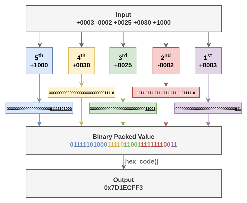
Figure 5.1.1: Bit extraction from 5 32-bit inputs to constitute a single 32-bit output
Examples
| Test Case | Input | Output |
|---|---|---|
| 1 | -0001 -0001 -0001 -0001 -0001 | 0xFFFFFFFF |
| 2 | +0001 +0001 -0001 -0001 -0001 | 0xFFFFF809 |
| 3 | +0003 -0002 +0025 +0030 +1000 | 0x7D1ECFF3 |
| 4 | +9999 +9999 +9999 +9999 +9999 | 0xE1EF787F |
Notes and Tips
- You may use the C operator for bit manipulation (<<, >>, |, &, ^, …) to implement your function. Suggested readings:
- You can test your code using the simulator's assistant from this link.
RISC-V Instruction Encoding
Instructions
Write a C program that reads a string with a RISC-V instruction from STDIN, parses its content in a way of obtaining its fields, packs the instruction's fields in a 32 bit value and writes the hexadecimal representation of the instruction to STDOUT.
The code snippet below can be used to compare strings as standard C libraries such as string.h are not available in the simulator. It is similar to string.h's strcmp but it has the number of characters to be compared as a parameter.
int strcmp_custom(char *str1, char *str2, int n_char){
    for (int i = 0; i < n_char; i++){
        if (str1[i] < str2 [i])
            return -1;
        else if (str1[i] > str2 [i])
            return 1;
    }
    return 0;
}
The set of instructions that need to be encoded by your program is presented in the table below, alongside its opcode, instruction type and other fields (e.g. funct3 and funct7) if applicable.
| Instruction | Inst Syntax | Inst Type | OPCODE | FUNCT3 | FUNCT7 |
|---|---|---|---|---|---|
| lui | lui rd, imm | U | 0110111 | N/A | N/A |
| auipc | auipc rd, imm | U | 0010111 | N/A | N/A |
| jal | jal rd, imm | J | 1101111 | N/A | N/A |
| jalr | jalr rd, imm(rs1) | I | 1100111 | 000 | N/A |
| beq | beq rs1, rs2, imm | B | 1100011 | 000 | N/A |
| bne | bne rs1, rs2, imm | B | 1100011 | 001 | N/A |
| blt | blt rs1, rs2, imm | B | 1100011 | 100 | N/A |
| bge | bge rs1, rs2, imm | B | 1100011 | 101 | N/A |
| bltu | bltu rs1, rs2, imm | B | 1100011 | 110 | N/A |
| bgeu | bgeu rs1, rs2, imm | B | 1100011 | 111 | N/A |
| lb | lb rd, imm(rs1) | I | 0000011 | 000 | N/A |
| lh | lh rd, imm(rs1) | I | 0000011 | 001 | N/A |
| lw | lw rd, imm(rs1) | I | 0000011 | 010 | N/A |
| lbu | lbu rd, imm(rs1) | I | 0000011 | 100 | N/A |
| lhu | lhu rd, imm(rs1) | I | 0000011 | 101 | N/A |
| sb | sb rs2, imm(rs1) | S | 0100011 | 000 | N/A |
| sh | sh rs2, imm(rs1) | S | 0100011 | 001 | N/A |
| sw | sw rs2, imm(rs1) | S | 0100011 | 010 | N/A |
| addi | addi rd, rs1, imm | I | 0010011 | 000 | N/A |
| slti | slti rd, rs1, imm | I | 0010011 | 010 | N/A |
| sltiu | sltiu rd, rs1, imm | I | 0010011 | 011 | N/A |
| xori | xori rd, rs1, imm | I | 0010011 | 100 | N/A |
| ori | ori rd, rs1, imm | I | 0010011 | 110 | N/A |
| andi | andi rd, rs1, imm | I | 0010011 | 111 | N/A |
| slli | slli rd, rs1, imm** | I | 0010011 | 001 | 0000000* |
| srli | srli rd, rs1, imm | I | 0010011 | 101 | 0000000* |
| srai | srai rd, rs1, imm | I | 0010011 | 101 | 0100000* |
| add | add rd, rs1, rs2 | R | 0110011 | 000 | 0000000 |
| sub | sub rd, rs1, rs2 | R | 0110011 | 000 | 0100000 |
| sll | sll rd, rs1, rs2 | R | 0110011 | 001 | 0000000 |
| slt | slt rd, rs1, rs2 | R | 0110011 | 010 | 0000000 |
| sltu | sltu rd, rs1, rs2 | R | 0110011 | 011 | 0000000 |
| xor | xor rd, rs1, rs2 | R | 0110011 | 100 | 0000000 |
| srl | srl rd, rs1, rs2 | R | 0110011 | 101 | 0000000 |
| sra | sra rd, rs1, rs2 | R | 0110011 | 101 | 0100000 |
| or | or rd, rs1, rs2 | R | 0110011 | 110 | 0000000 |
| and | and rd, rs1, rs2 | R | 0110011 | 111 | 0000000 |
* slli, srli and srai are type I instructions but its immediate takes up only 5 bits, the remaining 7 bits are filled with a funct7 value. ** The imm field may also appear as shamt, which stands for shift amount.
Input
- RV32I assembly instruction string with at most 40 bytes. There will be no pseudo-instructions, the registers will be referenced with their x-name (e.g. x2, x10), and immediate values will be in decimal.
Output
- The 32 bit encoded instruction in its Big Endian hexadecimal representation (hex_code() from the previous exercise can be used).
Examples
| Test Case | Input | Output |
|---|---|---|
| 1 | lb x10, 4(x9) | 0x00448503 |
| 2 | and x31, x20, x25 | 0x019A7FB3 |
| 3 | slti x12, x13, -1 | 0xFFF6A613 |
| 4 | bge x7, x0, 256 | 0x1003D063 |
| 5 | jalr x1, -32(x9) | 0xFE0480E7 |
Notes and Tips
- This exercise depends on some things used in Exercise 5.1, such as hex_code() and pack() functions, so it is recommended to do Exercise 5.1 first.
- You can use this base code as a starting point, or build your solution from scratch if you want.
- Refer to the RISC-V Instruction Set Manual to check how each instruction is encoded. Especially, consult the RV32I Base Instruction Set on page 609. For information regarding the encoding of immediates, check Section 2.3 on pages 26 and 27.
- You can test your code using the simulator's assistant from this link.
Assembly User-level Programming
This chapter presents exercises to be done using exclusively RISC-V Assembly Language, in order to fixate the concepts addressed on chapters 4, 5, 6 and 7 from the textbook.
Square Root
Instructions
Write a program in RISC-V assembly language that computes the approximated square root of integers.
To perform read and write of data from/to the terminal, you must use the read and write syscalls (similarly to exercise 3.1, but now in assembly language)
read syscall example:
    li a0, 0  # file descriptor = 0 (stdin)
    la a1, input_address #  buffer to write the data
    li a2, 1  # size (reads only 1 byte)
    li a7, 63 # syscall read (63)
    ecall

input_address: .skip 0x10  # buffer
write syscall example:
    li a0, 1            # file descriptor = 1 (stdout)
    la a1, string       # buffer
    li a2, 19           # size
    li a7, 64           # syscall write (64)
    ecall
string:  .asciz "Hello! It works!!!\n"
Input
- Four 4-digit decimal numbers separated by spaces (' '), followed by a newline character ('\n'). The whole input takes up 20 bytes.
- String Format - "DDDD DDDD DDDD DDDD\n"
- D: a decimal digit, (0-9)
Output
For each 4-digit number read, you must compute its approximate square root and write its value to STDOUT using 4-digits and each square root must be separated by a space (' ') and the last one is followed by a newline character ('\n'), so the output will also take up 20 bytes.
- String Format - "DDDD DDDD DDDD DDDD\n"
- D: a decimal digit, (0-9)
Examples
| Test Case | Input | Output |
|---|---|---|
| 1 | 0400 5337 2240 9166 | 0020 0073 0047 0095 |
Notes and Tips
-
The usage of Babylonian method with 10 iterations is recommended. Considering that we want to compute the square root of a number y, the basic idea of this method is:
-
Compute an initial guess for the square root: $$ k=\frac{y}{2} $$
-
Approximate your estimative, k, to the real value of the square root by applying the following equation:
$$ k'=\frac{k+\frac{y}{k}}{2} $$
-
Each time the above equation is applied is considered "one iteration". For this exercise, use 10 iterations.
-
-
For this exercise, approximate solutions are accepted.
- Solutions with an absolute error smaller than 10 will be considered correct.
-
Other methods to square root approximation can be used, as long as:
- It used only integers. Floating point numbers or the RISC-V square root instruction cannot be used.
- The approximation is as or more precise than the suggested method.
-
You can test your code using the simulator's assistant from this link.
GPS
Instructions
In this activity, you must write a program in RISC-V assembly language that computes your geographical coordinates in a bidimensional plane, based on the current time and messages received from 3 satellites.
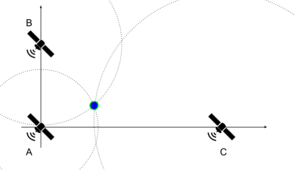
Figure 6.2.1: Satellites' Positions on the Plane
To simplify the exercise, it is assumed that satellite A is placed at the origin of the cartesian plane (0, 0), while B and C are positioned at (0, YB) and (XC, 0), respectively. The satellites continuously send messages with a timestamp, which marks when the message was sent, via waves that propagate in all directions at a speed of 3 x 10⁸ m/s. At a given time TR, you receive a message from each satellite containing the timestamps TA, TB, and TC. Assuming that all clocks are perfectly synchronized, print your coordinates (x, y) in the cartesian plane. Note that the formulation used in this exercise is not realistic.
Input
- Line 1 - Coordinates YB and Xc. Values are in meters, represented by 4-digit integers in decimal base and preceded by a sign ('+' or '-').
- Line 2 - Times TA, TB, Tc and TR. Values are in nanoseconds, represented by 4-digit integers in decimal base
Output
- Your coordinate - (x, y). Values are in meters, approximated, represented by 4-digit integers in decimal base and preceded by a sign ('+' or '-').
Examples
| Test Case | Input | Output |
|---|---|---|
| 1 | +0700 -01002000 0000 2240 2300 | -0088 +0016 |
| 2 | +1042 -20426823 4756 6047 9913 | -0902 -0215 |
| 3 | -2168 +02803207 5791 3638 9550 | +0989 -1626 |
| 4 | -2491 +09652884 7511 2033 9357 | -0065 -1941 |
| 5 | -0656 +13370162 2023 1192 9133 | +1255 -2381 |
Notes and Tips
- Multiple values written or read on/from the same line will be separated by a single space.
- Each line ends with a newline character '\n'.
- For this exercise, approximate solutions are accepted.
- Solutions with an absolute error smaller than 10 will be considered correct.
- The usage of the same method used in Exercise 6.1 with more iterations (e.g. 21 iterations) is recommended. Other methods to square root approximation can be used, as long as:
- It used only integers. Floating point numbers or the RISC-V square root instruction cannot be used.
- The approximation is as or more precise than the suggested method.
- It is best to work with distances in meters and time in nanoseconds, so that the provided input values do not cause overflow when using the proposed method and a good precision might be achieved.
- Problem Geometry:
- There are many ways to solve this exercise. Here, we propose an approach that uses the equation of a circle. Given that dA, dB and dC are the distances between your position and the satellites A, B and C, respectively:
- x2 + y2 = dA2 (Eq. 1)
- x2 + (y - YB)2 = dB2 (Eq. 2)
- (x - XC)2 + y2 = dC2 (Eq. 3)
- Using Equations 1 and 2:
- y = (dA2 + YB2 - dB2) / 2YB (Eq. 4)
- x = + sqrt(dA2 - y2) OR - sqrt(dA2 - y2) (Eq. 5)
- To find the correct x, you can try both possible values in Equation 3 and check which one is closer to satisfying the equation.
- There are many ways to solve this exercise. Here, we propose an approach that uses the equation of a circle. Given that dA, dB and dC are the distances between your position and the satellites A, B and C, respectively:
- You can test your code using the simulator's assistant from this link.
Hamming Code
Instructions
In this activity, you must write a program in RISC-V assembly language that performs the encoding and decoding of a Hamming(7, 4) code.
Encoding
For the first part of this exercise, you will receive a sequence of 4 bits, and you have to encode these data bits using the Hamming Code. Assuming that the 4 bit input is given as: d1d2d3d4
The output will be p1p2d1p3d2d3d4
The new inserted bits with radical p are parity bits. Each one of the 3 parity bits is responsible for reflecting the parity of a given subset of bits (subset of 3 elements from the 4 available input bits). A parity bit is 1 if the evaluated set of bits has an odd number of 1s, or 0 otherwise. The following table can be used as reference:
| Parity Bit | Subset of tested bits |
|---|---|
| p1 | d1d2d4 |
| p2 | d1d3d4 |
| p3 | d2d3d4 |
Decoding
On the second part of this exercise, you will receive a sequence of 7 bits that has been encoded. You have to extract the data field from this sequence, and also check if the data contains an error caused by a bit flip (there is no need for correcting the data if an error is detected). For this error checking, you have to verify the parity of each one of the 3 subsets.
The XOR operator can be used for a given subset of bits. For instance, to check the parity for which p1 is responsible, p1 XOR d1 XOR d2 XOR d4 must be equal to 0. Otherwise, there is an error on the encoded data. Do this for the 3 subsets of bits in order to check if you can trust the data encoded with Hamming(7, 4).
Input
- Line 1 - a sequence of 4 bits that must be encoded in a Hamming code using 3 parity bits, followed by a newline character (
\n). - Line 2 - a sequence of 7 bits that is Hamming encoded, and must be decoded and checked, followed by a newline character (
\n).
Output
- Line 1 - sequence of 7 bits that has been encoded using Hamming code, followed by a newline character (
\n). - Line 2 - sequence of 4 bits that has been decoded from the Hamming code, followed by a newline character (
\n). - Line 3 - 1 if an error was detected when decoding the Hamming code, 0 otherwise, followed by a newline character (
\n).
Examples
| Test Case | Input | Output |
|---|---|---|
| 1 | 10010011001 | 001100110010 |
| 2 | 00000000000 | 000000000000 |
| 3 | 00010010001 | 110100110011 |
| 4 | 11111001001 | 111111100011 |
| 5 | 10101011010 | 101101010100 |
Notes and Tips
- Exclusive OR (XOR) is a logic operator that facilitates the computation of parity bits
- AND instruction is useful to leave only a given group of bits set (masking).
- The decoded data doesn't need to be corrected, in case an error is detected.
- You can test your code using the simulator's assistant from this link.
Image on Canvas
Instructions
In this activity, you must write a program in RISC-V assembly language that reads an image in PGM format from a file and shows it on screen using the canvas peripheral.
Input
Your program must read a file called "image.pgm" that will be in the same directory as the executable file. The syscall open can be used to open the file (an example is shown at the Notes and Tips section)
Some examples of PGM images can be found on this site: PGMB Files - Binary Portable Gray Map Graphics Files. Smaller examples are also availabe here.
Output
Your program must show the image on the screen using syscalls to the Canvas peripheral. The Canvas must be adjusted to have the image size. The available syscalls are:
| syscall | Input | Description |
|---|---|---|
| setPixel | a0:pixel's x coordinatea1: pixel's y coordinatea2: concatenated pixel's colors: R|G|B|A
| Defines the color of a given canvas' pixel. For gray scale, use the same values for the colors (R = G = B) and alpha = 255. |
| setCanvasSize | a0:canvas width (value between 0 and 512)a1: canvas height (value between 0 and 512)a7: 2201 (syscall number) | Resets and defines canvas' size. |
| setScaling | a0: horizontal scalinga1: vertical scalinga7: 2202 (syscall number) | Updates canvas' scaling. Must be used only after all the canvas' pixels are set. |
Notes and Tips
- To test on the simulator, you have to load your program (.s file) and the image file (name "image.pgm") simultaneously.
- When new files are loaded to the simulator, older ones are erased, so you have to load the program and image files together every time.
- To use the Canvas, you must enable it on the simulator. To do so, go to the tab “Hardware” -> “External Devices” table -> “+” Icon on the Canvas row. A new tab will appear where the canvas can be seen.
- This exercise uses multiple syscall numbers. These values will always be stored on the register a7, and the ecall function has a different behavior for each value. To check the syscall for a specific functionality, the simulator table can be checked (note that the syscalls related to external devices, like Canvas, are not shown in this table if the device is not enabled).
- You will not receive images larger than 512x512 (that typically takes up 262159 bytes).
- You can either read the image byte per byte, or use a buffer large enough to store the whole image file content and perform a single read syscall.
- In all images, Maxval will be 255.
- The canvas is indexed starting on 0.
- You need to resize the canvas (setCanvasSize syscall) according to the file header.
- The setScaling syscall can be used to scale the resulting image, in order to inspect the resulting image. However, it must not be used when running with the assistant.
- You can test your code using the simulator's assistant from this link.
setPixel example:
    li a0, 100 # x coordinate = 100
    li a1, 200 # y coordinate = 200
    li a2, 0xFFFFFFFF # white pixel
    li a7, 2200 # syscall setPixel (2200)
    ecall
open example: The open syscall returns the file descriptor (fd) for the file on a0. This file descriptor must be used on the read syscall to indicate the file from which the operating system must read from to get the contents of the file.
    la a0, input_file    # address for the file path
    li a1, 0             # flags (0: rdonly, 1: wronly, 2: rdwr)
    li a2, 0             # mode
    li a7, 1024          # syscall open
    ecall

input_file: .asciz "image.pgm"
close example: The close syscall closes a file descriptor, so that it no longer refers to any file and may be reused.
    li a0, 3             # file descriptor (fd) 3
    li a7, 57            # syscall close
    ecall

input_file: .asciz "image.pgm"
Applying a Filter to an Image
Instructions
In this activity, you must write a program in RISC-V assembly language that reads an image in PGM format from a file, applies an edge detection filter and shows the result on screen using the canvas peripheral.
The first step of this exercise is to read an image in the PGM format and store its content in a matrix (exactly as done in exercise 6.4). After that, you must apply the following filter on the image:
$$ w = \begin{bmatrix} -1 & -1 & -1 \\\ -1 & 8 & -1 \\\ -1 & -1 & -1 \end{bmatrix} $$
Assuming \(w\) the filter matrix above, \(M_{in}\) the matrix representing the input image, and \(M_{out}\) the matrix representing the output image. The basic idea of applying the filter is that each \(M_{out}\) pixel[i, j] is defined as:
$$ M_{out}[i][j] = \sum_{k=0}^{2} \sum_{q=0}^{2} w[k][q] * M_{in}[i+k-1][j + q - 1] $$
Note that this can lead to the \(M_{in}\) matrix to be indexed with invalid indices (negative or out of bounds). In order to avoid these cases, the border pixels of the image \(M_{out}\) must be initialized with black and it is not necessary to compute the filter value for them. You can visualize how this filter works in Image Kernels explained visually (select the "outline" filter). This filter is also known as the Laplacian operator for edge detection.
Also note that the image pixels must have values between 0 (black) and 255 (white). If the result of the equation presented above is not in this interval, you must use the closest value in the interval (i.e., values lower than 0 become 0, and values greater than 255 become 255).
Input
Your program must read a file called "image.pgm" that will be in the same directory as the executable file, as explained in Exercise 6.4.
Output
Your program must show the result image on the screen, using the Canvas peripheral, as explained in Exercise 6.4.
Notes and Tips
- You need to resize the canvas (setCanvasSize syscall) according to the file header.
- Remember to correctly concatenate the pixel's colors in register a2 when using the setPixel syscall, as explained in Exercise 6.4. The output will be in gray scale, so use the same values for the colors (R = G = B) and alpha = 255.
- You can test your code using the simulator's assistant from this link.
Custom Search on a Linked List
Instructions
In this activity, you must write a program in RISC-V assembly language that receives a number via STDIN, goes through a linked list and prints the index of the node where the sum of the two stored values is equal to the number read from STDIN. In case none of the nodes in the linked list fill this requirement, the number -1 must be printed.
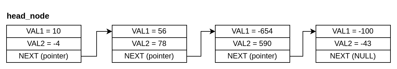
Figure 6.6.1: Linked List
For the linked list above, in case the input was 134, the number 1 (index of the second node on the list) should be printed as 56 + 78 = 134. If the input was a number that is not equal to the sum of any of the nodes (e.g. 8), -1 should be printed.
Input
An ASCII encoded decimal number on the interval -10000 and 10000.
Output
Index of the node where the sum of the two stored values is equal to the received value, if it exists on the linked list, -1 if it does not exist.
Examples
Example of data.s file that will be linked to your program:
.globl head_node

.data
head_node:
    .word 10
    .word -4
    .word node_1
.skip 10
node_1:
    .word 56
    .word 78
    .word node_2
.skip 5
node_3:
    .word -100
    .word -43
    .word 0
node_2:
    .word -654
    .word 590
    .word node_3
| Test Case | Input | Output |
|---|---|---|
| 1 | 6 | 0 |
| 2 | 45 | -1 |
| 3 | -64 | 2 |
Notes and Tips
- The head node of the linked list is stored on the address marked by the label head_node (DO NOT use this label on your code).
- The fields of the linked list node struct are VAL1, VAL2, and NEXT, in this order. VAL1 and VAL2 are 32-bit signed integer values stored on the node and NEXT is the pointer to the next node on the linked list. If there isn't a next node, it will be a NULL pointer.
- To check if the received value is on the current node, the comparison VAL1 + VAL2 = received value must be made.
- A NULL pointer is represented by the value 0.
- The indexing of the list nodes starts at 0 (i.e. the head_node has index 0), and the linked list will have up to 1000 nodes in the test cases.
- All nodes will have different sum values.
- You can test your code using the simulator's assistant from this link.
ABI-compliant Linked List Custom Search
Instructions
In this activity, you must write a program in RISC-V assembly language that has a ABI-compliant function int linked_list_search(Node *head_node, int val), similar to the one implemented in exercise 6.6. Your code will be linked to a code in C that calls the linked_list_search function and expects the return value to be the index of the node where the sum of the values is equal to val or -1 in case there isn't such a node on the linked list.
In addition to linked_list_search, you will need to implement a few utility functions that will be required for this exercise and future ones. There is no need to handle errors nor end-of-file (EOF).
-
void puts ( const char * str );
Description Parameters Return Value puts - C++ Reference String terminated by \0 - -
char * gets ( char * str );
Description Parameters Return Value gets - C++ Reference Buffer to be filled Check function documentation -
int atoi (const char * str);
Description Parameters Return Value atoi - C++ Reference String terminated by \0 Integer represented by the string -
char * itoa ( int value, char * str, int base );
Description Parameters Return Value itoa - C++ Reference Check function documentation. Only bases 10 and 16 will be tested. The tests won't be case-sensitive. - -
void exit(int code);
Description Parameters Return Value Calls exit syscall to finish execution. Return code (usually used as error code). -
lib.h:
typedef struct Node {
    int val1, val2;
    struct Node *next;
} Node;

int linked_list_search(Node *head_node, int val);
void puts ( const char *str );
char *gets ( char *str );
int atoi (const char *str);
char *itoa ( int value, char *str, int base );
void exit(int code);
Input
Test Case index and specific input depending on the test case (check example.c).
Output
Output according to the test case.
Notes and Tips
- The linked_list_search function will receive the address of the head node on register a0 and the value being searched on register a1, and must return on the register a0 the index of the node, if found, or -1 otherwise.
- The fields of the linked list node struct are VAL1, VAL2 and NEXT, in this order. VAL1 and VAL2 are the signed int values stored on the node and NEXT is the pointer to the next node on the linked list. If there isn't a next node, it will be a NULL pointer.
- To check if the received value is on the current node, the comparison VAL1 + VAL2 = received value must be made.
- A NULL pointer is represented by the value 0.
- The indexing of the list nodes starts at 0 (i.e. the head_node has index 0), and the linked list will have up to 1000 nodes in the test cases.
- All nodes will have different sum values.
- Symbols must be set as global (
.globldirective) for the linker to resolve undefined references. - The character
\0corresponds to the null byte, which has the value 0. However, usingli a0, '\0'will lead to errors because the assembler interprets the value as the character'0'(which has an ASCII value of 48) rather than the null byte. - You can test your code using the simulator's assistant from this link.
ABI-compliant Recursive Binary Tree Search
Instructions
In this activity, you must write a program in RISC-V assembly language that has a ABI-compliant recursive function int recursive_tree_search(Node *root, int val). Your code will be linked to a code in C that calls the recursive_tree_search function and expects the return value to be the depth of the value if the searched value is present on the tree, 0 if not.
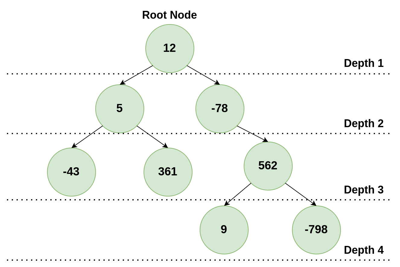
Figure 6.8.1: Binary Tree
The image above shows an example of a binary tree. If the value 361 was being searched, 3 would be the return value of the function, as it is the depth of the value in the tree.
Each tree node is a struct that contains a value on its first position, pointers to the left child and right child on the second and third positions, respectively. In case one of the children does not exist, the pointer will be NULL
lib.h:
typedef struct Node {
    int val;
    struct Node *left, *right;
} Node;

int recursive_tree_search(Node *root_node, int val);
void puts ( const char *str );
char *gets ( char *str );
int atoi (const char *str);
char *itoa ( int value, char *str, int base );
void exit(int code);
Input
Your function will receive the address of the root of the tree on register a0 and the value being searched on register a1.
Check the file example.c to see how your functions will be called. The binary tree used in this example is the same as presented in Figure 6.8.1.
Output
Your function must return on the register a0 the depth of the value if the searched value is present on the tree, 0 otherwise.
Examples
| Test Case | Input | Output |
|---|---|---|
| 1 | 12 | 1 |
| 2 | 562 | 3 |
| 3 | -40 | 0 |
Notes and Tips
- The root node has depth 1.
- The fields of the binary tree node struct are VAL, LEFT and RIGHT, in this order. VAL is a signed int value stored on the node and LEFT and RIGHT are pointers to the node's children. If a node doesn't have one of these - children, the respective pointer will be NULL.
- To check if the received value is on the current node, the comparison VAL = received value must be made.
- A NULL pointer is represented by the value 0.
- All nodes will have different values.
- The utility functions implemented in exercise 6.7 are necessary in this exercise.
- You can test your code using the simulator's assistant from this link.
Assembly System-level Programming
This chapter contains exercises related to System-level programming, which is explored in chapters 8, 9 and 10 from the textbook.
Accessing Peripherals - Controlling the Car
Instructions
In this activity, you must control a car to move it from a parking lot to the entrance of the Test Track (shown in the picture below) in, at most, 180 seconds. The car is an external device connected to the RISC-V processor and can be controlled by syscalls or MMIO.
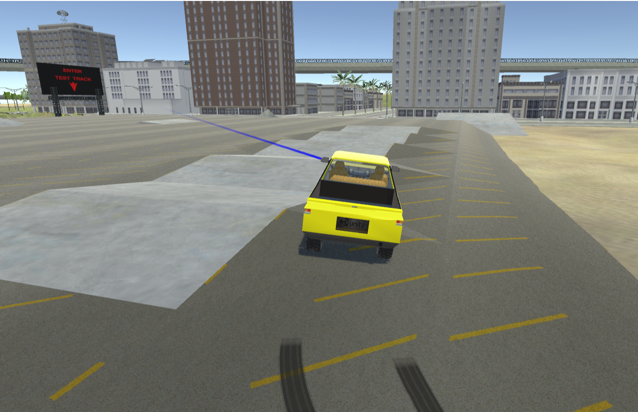
Figure 7.1.1: Car Simulation
- In this exercise, you must use only MMIO to control the car. The MMIO specifications for the peripherals of the simulator can be seen in the ALE Peripheral MMIO Manual.
- You only need to use MMIO to control the steering wheel, engine, brakes and get coordinates.
- The entrance to the Test Track is placed at:
- x: 73, y: 1, z: -19
- The base address is shown at the table "Memory Map" (see example below)
- The car will be considered to have reached its destination when it reaches a point inside a radius of 15 meters from the Test Track entrance. Your code must call the exit syscall to finalize the execution.
Infrastructure
In order to use the car, first you must enable the device 'Self-Driving Car' on the RISC-V simulator. This can be done on the tab 'Hardware' and selecting the device ‘Self-Driving Car’ as shown in the picture below.
After adding the device, its base address will be listed on the table:
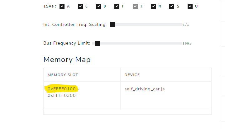
Figure 7.1.2: Memory Map Table
The car can be accessed through 'Self-driving car', on the left bar, as shown in the picture below. The car icon can take a while to appear for the first time.
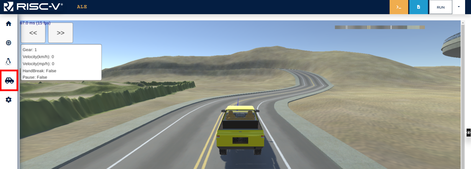
Figure 7.1.3: Car Menu Tab
Note that, after adding the device, the car will be placed in an arbitrary position. Use the Assistant to place the car inside the parking lot.
In addition to that, you can test moving the car manually using the arrow keys or WASD. To do so, enable the option ‘Enable debug controls’ on the simulator, as demonstrated below.
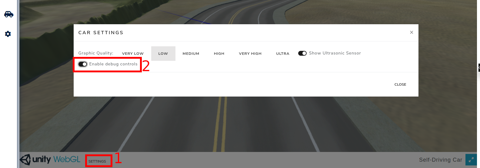
Figure 7.1.4: Debug Controls
Notes and Tips
- Check the ALE Peripheral MMIO Manual for information about the Self Driving Car peripheral.
- The starting point and destination are fixed. You have to use the assistant to place the car at the starting point (there is a button on the assistant that can be used for that).
- The steering wheel direction values range from -127 to 127, negative values steer to the left and positive values to the right.
- For debugging purposes, you can control the car when the test fails, using the keys WASD or arrow keys, with the option ‘‘Enable debug controls’’ enabled. However, this option can't be enabled while your code is running on the simulator.
- You can test your code using the simulator's assistant from this link.
Accessing Peripherals - Using Serial Port
Instructions
In this activity, you will communicate with the Serial Port device via MMIO. You will need to read a stream of bytes from the Serial Port and then perform an operation on top of the data read.
Interactions with Serial Port can be done through two memory addresses:
- base+0x00: storing the value 1 triggers a write, writing the byte that is stored at base+0x01. The byte at base+0x00 is set to 0 when write is complete.
- base+0x02: storing the value 1 triggers a read, reading one byte and storing it at base+0x03. The byte at base+0x02 is set to 0 when read is complete.
There will be 4 different sets of operations to perform:
- Operation 1: read a string and write it back to Serial Port
- Input: 1\n{string with variable size}\n
- Output: {string with variable size}\n
- Operation 2: read a string and write it back to Serial Port reversed
- Input: 2\n{string with variable size}\n
- Output: {string with variable size reversed}\n
- Operation 3: read a number in decimal representation and write it back in hexadecimal representation. Use uppercase letters.
- Input: 3\n{decimal number with variable size}\n
- Output: {number in hexadecimal}\n
- Operation 4: read a string that represents an algebraic expression, compute the expression and write the result to Serial Port.
- Input: 4\n{number with variable size} {operator} {number with variable size}\n
- Output: {operation result in decimal representation}\n
- Operator can be + (add) , - (sub), * (mul) or / (div)
Examples
| Test Case | Input | Output |
|---|---|---|
| 1 | 1Random String | Random String |
| 2 | 2Reversed String | gnirtS desreveR |
| 3 | 31876 | 754 |
| 4 | 4244 + 67 | 311 |
| 5 | 42340 / 50 | 46 |
Notes and Tips
- Check the ALE Peripheral MMIO Manual for information about the Serial Port peripheral.
- You can debug your program reading from STDIN and writing to STDOUT. Before testing with the Assistant, the functions responsible for IO need to be changed in order to interact with the Serial Port.
- The final version of your program can't use syscalls except for the exit syscall.
- You can use the program stack to store strings with variable sizes.
- You can test your code using the simulator's assistant from this link.
External Interrupts - MIDI Player
Instructions
In this activity, you must implement a library that will be used by a MIDI audio player. The peripherals used in this activity are the MIDI Synthesizer and General Purpose Timer (GPT), and their description can be found in the ALE Peripheral MMIO Manual. Your library will have three main functionalities:
- Implement a _start function, that initializes the program's stack (see Notes and Tips for more information on how to do that), sets interrupts, and calls the main function (using the jal instruction), available in the provided application.
- Note that the jal instruction will be used, as it won't be necessary to change execution mode. In future exercises, this may be necessary (and mret will be used instead of jal).
- Program and handle external interrupts of a timer device (GPT).
- The GPT interrupt handler must simply increment a global time counter (_system_time), that needs to be initialized as zero.
- We suggest programming GPT to generate interrupts every 100 ms, which is the value that must be incremented in _system_time.
- After handling the interrupt, the
mretinstruction must be used to resume the user code execution.
- Provide a function “play_note” to access the MIDI Synthesizer peripheral through MMIO.
- The function prototype is void play_note(int ch, int inst, int note, int vel, int dur);
- The parameters are:
- ch: channel;
- inst: instrument ID;
- note: musical note;
- vel: note velocity;
- dur: note duration.
Notes and Tips
- Check the ALE Peripheral MMIO Manual for information about the MIDI Synthesizer and General Purpose Timer peripherals.
- To allocate the stacks, you can declare two arrays in your program. When initializing the stack pointer (SP), remember that RISC-V stacks are full-descending.
- You must implement all the functions in a single file lib.s, in RISC-V assembly language.
- We provide our application in the file midi-player.c, that uses your library and mustn't be changed. This file must be uploaded with the .s library file.
- All functions must follow the ABI.
- All functions must be thread-safe. Right now, you don't need to understand this concept. Just ensure that your code doesn't use global variables (the only exceptions are the variables _system_time, the program and ISR stacks). Use only local variables, allocated on the stack or on registers.
- Simulator configuration:
- To receive external interrupts, set the “Bus Controller Frequency Scaling” on the "Hardware" tab to 1/27.
- Also on the "Hardware" tab, add the GPT, and after that, the Sound Synthesizer (MIDI), in this order.
- Before beginning to test the MIDI Synthesizer, check the volume of your browser and computer. Some notes from The White Stripes' Seven Nation Army will be played.
- You must access the peripherals through MMIO, just like Exercises 7.1 and 7.2.
- Each device's base_addr can be seen on the table “Memory Map” in the "Hardware" tab.
- You can test your code using this simulator setup, but there isn't an assistant for this exercise.
Software Interrupts - Controlling the Car
Instructions
In this exercise, you will do the same activity as Exercise 7.1: you must control a car to move it from a parking lot to the entrance of the Test Track. However, you can no longer access the MMIO addresses directly on user code, i.e., the high-level code with the control logic. You must implement a set of syscalls to control the car and use them in your control logic, that has to be executed in user mode.
Separating the control code
The following code is suggested as a starting point for your solution. You can change it however you want.
.text
.align 4

int_handler:
  ###### Syscall and Interrupts handler ######

  # <= Implement your syscall handler here

  csrr t0, mepc  # load return address (address of
                 # the instruction that invoked the syscall)
  addi t0, t0, 4 # adds 4 to the return address (to return after ecall)
  csrw mepc, t0  # stores the return address back on mepc
  mret           # Recover remaining context (pc <- mepc)


.globl _start
_start:

  la t0, int_handler  # Load the address of the routine that will handle interrupts
  csrw mtvec, t0      # (and syscalls) on the register MTVEC to set
                      # the interrupt array.

# Write here the code to change to user mode and call the function
# user_main (defined in another file). Remember to initialize
# the user stack so that your program can use it.

.globl control_logic
control_logic:
  # implement your control logic here, using only the defined syscalls
You must create a second file, called main.s, that contains only the code below. This code can't be changed and will be used by the assistant to check your solution.
.text
.globl user_main
user_main:
  jal control_logic
infinite_loop:
  j infinite_loop
Syscalls
You can implement the system calls listed below. In case your code doesn't use some of them, it is not necessary to implement it. For this exercise, you mustn't implement any additional system calls.
| syscall | Parameters | Return Value | Description |
|---|---|---|---|
| syscall_set_engine_and_steeringCode: 10 | a0: Movement directiona1: Steering wheel angle | 0 if successful and -1 if failed (invalid parameters) | Start the engine to move the car.a0's value can be -1 (go backward), 0 (off) or 1 (go forward).a1's value can range from -127 to +127, where negative values turn the steering wheel to the left and positive values to the right. |
| syscall_set_hand_brakeCode: 11 | a0: value stating if the hand brakes must be used | - | a0 must be 1 to use hand brakes. |
| syscall_read_line_cameraCode: 12 | a0: address of an array with 256 elements that will store the values read by the Line Camera. | - | Read values from the Line Camera. |
| syscall_get_positionCode: 15 | a0: address of the variable that will store the value of x position.a1: address of the variable that will store the value of y position.a2: address of the variable that will store the value of z position. | - | Read the car's approximate position using the GPS device. |
Notes and Tips
- Check the ALE Peripheral MMIO Manual for information about the Self Driving Car peripheral.
- If you are not using the assistant, you must configure the simulator in a similar way as done for Exercise 7.1. However, with a small difference: the option “Enable Operating System” must stay disabled.
- You mustn't call the exit syscall (as there isn't an operating system, it doesn't exist).
- The syscall operation code must be passed via register a7, as done in previous exercises.
- You can test your code using the simulator's assistant from this link.
Complementary Short Exercises
This chapter contains complementary short exercises for topics explored in previous chapters.
ABI Compliance
-
Write a program with a global variable named
my_varof type int (32 bits), initialized with the value 10 and a functionvoid increment_my_var()that increments 1 to this global variable. -
Write a program that uses only caller-save registers and the sp and ra registers, it must have a function called 'my_function' that receives three values and does the following:
-
Computes the sum of the first two values:
SUM 1 -
Calls a function called
mystery_functionpassingSUM 1and the first value as parameters in this order:CALL 1 -
Computes the difference between the second value and the returned value of the
mystery_function(CALL 1):DIFF 1 -
Sums the third value to the difference (
DIFF 1):SUM 2 -
Calls
mystery_functionagain passing the sum above (SUM 2) and the second value as parameters in this order:CALL 2 -
Computes the difference between the third value and the returned value of the
mystery_functionabove (CALL 2):DIFF 2 -
Sums the difference above (
DIFF 2) withSUM 2:SUM 3 -
Returns
SUM 3 -
The C code below exemplifies these steps
int my_function(int a, int b, int c){
int aux = b - mystery_function(a+b, a) + c;
return c - mystery_function(aux, b) + aux;
};
-
-
Convert the following C function to assembly code. Note:
charandshortvalues are extended to 32 bits when stored in the program stack.int operation(){ int a = 1; int b = -2; short c = 3; short d = -4; char e = 5; char f = -6; int g = 7; int h = -8; char i = 9; char j = -10; short k = 11; short l = -12; int m = 13; int n = -14; return mystery_function(a, b, c, d, e, f, g, h, i, j, k, l, m, n); } -
Convert the following C function to assembly code. Note:
charandshortvalues are extended to 32 bits when stored in the program stack.int operation(int a, int b, short c, short d, char e, char f, int g, int h, char i, char j, short k, short l, int m, int n){ return b + c - f + h + k - m; }; -
Convert the following C function to assembly code.
int operation(int a, int b, int c, int d, int e, int f, int g, int h, int i, int j, int k, int l, int m, int n){
    return mystery_function(n, m, l, k, j, i, h, g, f, e, d, c, b, a);
};
Data Organization on the Memory
-
Convert the following C functions to assembly code.
int swap_int(int *a, int *b){ int aux = *a; *a = *b; *b = aux; return 0; }; int swap_short(short *a, short *b){ short aux = *a; *a = *b; *b = aux; return 0; }; int swap_char(char *a, char *b){ char aux = *a; *a = *b; *b = aux; return 0; }; -
Convert the following C functions to assembly code.
int middle_value_int(int *array, int n){ int middle = n / 2; return array[middle]; }; short middle_value_short(short *array, int n){ int middle = n / 2; return array[middle]; }; char middle_value_char(char *array, int n){ int middle = n / 2; return array[middle]; }; int value_matrix(int matrix[12][42], int r, int c){ return matrix[r][c]; }; -
Convert the following C functions to assembly code, using the program stack to store local variables.
int fill_array_int(){
    int array[100];
    for (int i = 0; i < 100; i++)
        array[i] = i;
    return mystery_function_int(array);
};

int fill_array_short(){
    short array[100];
    for (short i = 0; i < 100; i++)
        array[i] = i;
    return mystery_function_short(array);
};

int fill_array_char(){
    char array[100];
    for (char i = 0; i < 100; i++)
        array[i] = i;
    return mystery_function_char(array);
};
For exercises 4 and 5, the following struct must be used
typedef struct Node {
  int a;
  char b, c;
  short d;
} Node;
-
Convert the following C function to assembly code.
int node_op(Node *node){ return node->a + node->b - node->c + node->d; }; -
Convert the following C function to assembly code, using the program stack to store local variables.
int node_creation(){
    Node node;
    node.a = 30;
    node.b = 25;
    node.c = 64;
    node.d = -12;
    return mystery_function(&node);
};
Stack and Frame Pointers
Proper management of the stack pointer and frame pointer is essential to avoid issues such as buffer overflows during recursion. It also assists in debugging, as correctly setting up the function's stack frame enables debugging tools to generate accurate stack traces.
The figure below shows a properly set up stack frame.
The last position (higher address) of the stack frame is used to save the return address register (ra), and the second to last is used for the old frame pointer (fp).
Then, the stack pointer (sp) can be update to allocate memory space on the stack for the current function, and the frame pointer is used to store the previous sp value (top of the stack for the previous function scope).
The memory space between sp and fp encompasses the stack frame of the current function.
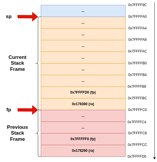
Figure 8.3.1: Function Stack Frame
-
Convert the following C functions to assembly code.
int factorial(int n){ mystery_function(); if (n < 2){ return 1; } return n*factorial(n-1); } -
Convert the following C functions to assembly code.
int fibonacci(n){ mystery_function(); if (n > 1) { return fibonacci(n-1) + fibonacci(n-2); } return n; }; -
Convert the following C functions to assembly code.
void reverse_str(char *str, int start, int end) { mystery_function(); if (start >= end) return; char temp = str[start]; str[start] = str[end]; str[end] = temp; reverse_str(str, start + 1, end - 1); } -
Convert the following C function to assembly code.
typedef struct Node { struct Node *left, *right; } Node; int tree_depth(Node *root){ mystery_function(); if (root == NULL){ return 0; } int left = tree_depth(root->left); int right = tree_depth(root->right); int max = (left > right) ? left : right; return max + 1; } -
Convert the following C function to assembly code, using the program stack to store local variables.
void merge(int* array, int left, int mid, int right) {
    int n_left = mid - left + 1;
    int n_right = right - mid;

    int L[n_left], R[n_right]; // These arrays should be created using malloc, but we will use use the program stack to store these arrays. Since array will have at most 30 values, 120 bytes should be enough to store the largest L and R together

    for (int i = 0; i < n_left; i++){
        L[i] = array[left + i];
    }
    for (int j = 0; j < n_right; j++){
        R[j] = array[mid + 1 + j];
    }

    int i = 0, j = 0, k = left;
    while (i < n_left && j < n_right) {
        if (L[i] <= R[j]){
            array[k++] = L[i++];
        } else {
            array[k++] = R[j++];
        }
    }

    while (i < n_left) {
        array[k++] = L[i++];
    }
    while (j < n_right){
        array[k++] = R[j++];
    }
}

void merge_sort(int* array, int left, int right) {
    mystery_function();
    if (left < right) {
        int mid = left + (right - left) / 2;
        merge_sort(array, left, mid);
        merge_sort(array, mid + 1, right);
        merge(array, left, mid, right);
    }
}
Final Projects
The last chapter contains a set of projects that encapsulates all concepts worked on previous chapters.
Driving Through the City
In this project you will develop the software layers responsible for the control of an autonomous car. The layers are illustrated in the picture below.
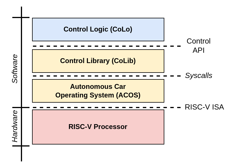
Figure 9.1.1: Software Layers
The ACOS layer is responsible for managing the hardware. It must provide a set of services for the CoLib layer through syscalls. The ACOS layer also contains the code that will be executed in machine mode and must be implemented in RISC-V assembly language.
The CoLib is responsible for providing a friendly programming interface for the Control Logic, called Control API. This layer also must be implemented in assembly language, but its code must be executed in user mode.
The CoLo layer is responsible for the logic that controls the car and uses functions defined by the Control API, implemented by CoLib. An initial version of this layer is available in this file. This version should work correctly if all the other layers have been fully and efficiently implemented, but you can also modify it in case it is necessary. It was implemented in C and must be executed in user mode.
CoLo Layer
The code for the CoLo layer is already implemented in C and uses the routines available in the Control API to send commands to the car. Your main function is to control the car, but it must also use the API to print timestamps of the arrival of the car on the checkpoints.
Control Logic of the Car
The car must perform a set of 3 routes through the city, being that the route is determined by a linked list that contains the coordinates of the next checkpoint and the action that must be performed when arriving there. The actions can be:
- GoForward (0): the car remains in the same direction it was headed.
- TurnLeft (1): the car must turn to the left.
- Turn Right (2): the car must turn to the right.
- GoBack (3): the car must perform a maneuver to head back where it came from.
- End (4): no action is performed, and indicates the end of the route.
The linked_lists.s file has 3 linked lists with head nodes A_0, B_0 and C_0.
CoLib Layer
The CoLib layer must implement the routines of the Control API in RISC-V assembly language. The API routines are listed in the header file control_api.h and must be implemented in the colib.s file. To interact with the hardware, the code must use syscalls, defined in the next section.
ACOS Layer
The ACOS layer must be implemented in assembly language in the file named acos.s, and must provide the syscalls listed in the table below. You must not implement additional syscalls besides the ones in the table.
Syscalls
| syscall | Parameters | Return Value | Description |
|---|---|---|---|
| syscall_set_engine_and_steeringCode: 10 | a0: Movement directiona1: Steering wheel angle | 0 if successful and -1 if failed (invalid parameters) | Start the engine to move the car.a0's value can be -1 (go backward), 0 (off) or 1 (go forward).a1's value can range from -127 to +127, where negative values turn the steering wheel to the left and positive values to the right. |
| syscall_set_hand_brakeCode: 11 | a0: value stating if the hand brakes must be used | - | a0 must be 1 to use hand brakes. |
| syscall_read_sensorsCode: 12 | a0: address of an array with 256 elements that will store the values read by the luminosity sensor. | - | Read values from the luminosity sensor. |
| syscall_read_sensor_distanceCode: 13 | - | Value obtained on the sensor reading; -1 in case no object has been detected in less than 20 meters. | Read the value from the ultrasonic sensor that detects objects up to 20 meters in front of the car. |
| syscall_get_positionCode: 15 | a0: address of the variable that will store the value of x position.a1: address of the variable that will store the value of y position.a2: address of the variable that will store the value of z position. | - | Read the car's approximate position using the GPS device. |
| syscall_get_rotationCode: 16 | a0: address of the variable that will store the value of the Euler angle in x.a1: address of the variable that will store the value of the Euler angle in y.a2: address of the variable that will store the value of the Euler angle in z. | - | Read the global rotation of the car's gyroscope. device. |
| syscall_read_serialCode: 17 | a0: buffera1: size | - | Reads up to size bytes from Serial Port |
| syscall_write_serialCode: 18 | a0: buffera1: size | - | Writes a buffer to Serial Port. |
| syscall_get_positionCode: 20 | - | Time since the system has been booted, in milliseconds. | Returns the time since the system has been booted, in milliseconds. |
Booting the system
When booting the system, ACOS must transfer the execution to the control application in user mode. To do so, ACOS must:
- Configure the user and system stacks;
- Change to user mode;
- Point the execution flow to the main function of the user program.
Notes and Tips
- We recommend using the Google Chrome browser (it was tested more extensively)
- Check if the frames per second (FPS) shown in the car screen is around 60. If it is much lower than that, your simulator can be too slow and the tests may fail due to timeout.
- The “Enable Operating System” option must be disabled.
- The devices must be added to the simulator in the following order
- GPT
- Self-Driving Car
- Serial Port
- You can enable the option “Enable debug controls” to get to know the road. To do so, use the arrow keys or WASD to move the car. This option must be disabled when testing/running your code.
- The syscall operation code must be passed by the a7 register.
- To initialize the user stack, just set the sp register with the value 0x07FFFFFC.
- Allocate the system stack in the .bss section.
- You can test your syscalls implementations using the Syscall Assistant - in this case, you must upload only acos.s, and the devices must not be added to the simulator.
- You can test your control library implementation using the Control Library Assistant - in this case, you must upload only acos.s and colib.s. This file shows how the functions are being tested.
- You can test your solution using the links Route A, Route B, and Route C - In this case, you must upload acos.s, colib.s, control_api.h, and colo.c files.
Appendix
ALE Peripherals MMIO Manual
Canvas
| Address | Size | Description |
|---|---|---|
base+0x00 | byte | Storing 1 triggers the canvas to write an array of up to 504 bytes representing up to 126 pixels to the screen. The register is set to 0 when writing is completed. |
base+0x02 | half | Array size (in bytes). |
base+0x04 | word | The initial position to write the array on the canvas. The canvas is represented as a 512x512x4-byte one-dimensional array representing 512x512 pixels. |
base+0x08tobase+0x200 | word | 504-byte array representing up to 126 pixels. Each pixel takes 4 bytes, one byte for each value: Red, Green, Blue, and Alpha (in this order). |
General Purpose Timer
| Address | Size | Description |
|---|---|---|
base+0x00 | byte | Storing 1 triggers the GPT device to start reading the current system time. The register is set to 0 when the reading is completed. |
base+0x04 | word | Stores the time (in milliseconds) at the moment of the last reading by the GPT. |
base+0x08 | word | Storing v > 0 programs the GPT to generate an external interruption after v milliseconds. It also sets this register to 0 after v milliseconds (immediately before generating the interruption). |
MIDI Synthesizer
| Address | Size | Description |
|---|---|---|
base+0x00 | byte | Storing ch ≥ 0 triggers the synthesizer to start playing a MIDI note in the channel ch. |
base+0x02 | short | Instrument ID. |
base+0x04 | byte | Note. |
base+0x05 | byte | Note velocity. |
base+0x06 | short | Note duration. |
Self Driving Car
| Address | Size | Description |
|---|---|---|
base+0x00 | byte | Storing 1 triggers the GPS device to start reading the coordinates and rotation of the car. The register is set to 0 when the reading is completed. |
base+0x01 | byte | Storing 1 triggers the Line Camera device to capture an image. The register is set to 0 when the capture is completed. |
base+0x02 | byte | Storing 1 triggers the Ultrasonic Sensor device to measure the distance in front of the car. The register is set to 0 when the measurement is completed. |
base+0x04 | word | Stores the Euler angle X of the car rotation at the moment of the last reading by the GPS. |
base+0x08 | word | Stores the Euler angle Y of the car rotation at the moment of the last reading by the GPS. |
base+0x0C | word | Stores the Euler angle Z of the car rotation at the moment of the last reading by the GPS. |
base+0x10 | word | Stores the X-axis of the car position at the moment of the last reading by the GPS. |
base+0x14 | word | Stores the Y-axis of the car position at the moment of the last reading by the GPS. |
base+0x18 | word | Stores the Z-axis of the car position at the moment of the last reading by the GPS. |
base+0x1C | word | Stores the distance (in centimeters) between the Ultrasonic sensor and the nearest obstacle. Returns -1 if there’s no obstacle within 20m. |
base+0x20 | byte | Sets the steering wheel direction. Negative values indicate steering to the left, positive values indicate steering to the right. |
base+0x21 | byte | Sets the engine direction.1: forward.0: off.-1: backward. |
base+0x22 | byte | Sets the hand break. (1 = enabled) |
base+0x24 | 256-byte array | Stores the image captured by the Line Camera. Each byte represents the luminance of a pixel. |
Serial Port
The serial port is connected to the terminal (stdout and stdin).
| Address | Size | Description |
|---|---|---|
base+0x00 | byte | Storing 1 triggers the serial port to write (to the stdout) the byte stored at base+0x01. The register is set to 0 when writing is completed. |
base+0x01 | byte | Byte to be written. ID |
base+0x02 | byte | Storing 1 triggers the serial port to read (from the stdin) a byte and store it at base+0x03. The register is set to 0 when reading is completed. |
base+0x03 | byte | Byte read. NULL (0) when stdin is empty. |
|