RISC-V ALE Manual
Manual for RISC-V ALE Simulator
Contributors:
- João Seródio
- Edson Borin
Introduction
This manual aims to present the main concepts and interfaces for using the RISC-V ALE simulator.
Chapter 1 provides an overview of the ALE simulator, Chapter 2 outlines the process of generating and inspecting RISC-V code. Chapter 3 discusses the different ways of running code in the simulator and their functionalities. Chapter 4 presents the main peripherals of the simulator. Finally, Chapter 5 and 6 explain how to develop new execution assistants and design new peripherals for the simulation environment.
Overview of the ALE Simulator
The ALE simulator is a web-based assembly simulator ecosystem, built on top of the CHIPS Alliance VeeR-ISS simulator. ALE consists of a set of WebAssembly artifacts and JavaScript (JS) code, that enables the execution of VeeR-ISS in the browser with an interactive user interface (UI). The UI provides functionalities that allow the user to load files, set syscalls and inputs to the program, and enable/disable external devices. In order to start the simulator, the user can either use the UI buttons (RUN, Debug, or Assistant->Run Tests) or use the terminal. When using the buttons, the terminal will be popped open and display the commands that are being executed, these commands can be run in the terminal in a standalone manner, if necessary.
Figure 1.0.1 shows an overview of the components that make up the simulator. Whisper, CLANG and LLD are third party softwares that were compiled to WebAssembly. Whisper is the RISC-V simulator, CLANG and LLD are LLVM compilation tools made available to run in the browser, facilitating code generation. They are exposed by using a JS wrapper that uses event handling and message passing to interact with the remaining components. The Assistant Script is a customizable component that can dictate how to execute a given program with a set of inputs and expected outputs, this custom logic is encoded in a URL. The peripherals are external devices that can be enabled, they are components with a fixed logic and are used to simulate the interaction with external devices. Most of the peripherals are pure JS code, but the Self-Driving Car and Uóli are Unity simulations with a JS wrapper that provides an interface to the peripheral to handle events. Assistant Scripts and Peripherals are explained in more detail in chapters 5 and 6 respectively. Lastly, the bus represents the common stream of events/messages of the web application that all the components listen to and handle according to their logic.
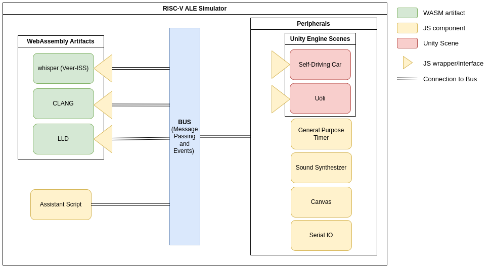
Figure 1.0.1: RISC-V ALE Components.
Code Generation and Code Inspection
Understanding the compilation workflow and the tools available in the code generation ecosystem are important prerequisites when it comes to working with assembly programming. This chapter presents a small overview of these topics.
Tools used in this chapter
There are several tools to generate and inspect source and binary code. For example, both the GNU GCC and CLANG tools can be used to compile C source code. The following tools are used in this manual.
Appendix A contains instructions to install both tools.
Overview of the Compilation Process
The compilation process of a C language program involves three main stages:
- Compilation: Each file with C code (with a
.cextension) is translated into assembly language code (files with a.sextension). - Assembly: The assembler reads the assembly language files and produces an object code (with a
.oextension on Linux). Note that complex software may consist of multiple source code files, resulting in various object files during the compilation process. Even though object files contain machine language code, they are not executable as the binary code is still separated into different object files and needs to be "linked" into a single file containing the entire code. - Linking: The linker reads multiple object files as input, links them together, and also links code from libraries.
The result is the final executable, the program that can be run by the user.
Figure 2.1 illustrates the compilation process of software with two source files:
source1.candsource2.c. In this diagram, thegcc -Scommand invokes the compiler, theascommand invokes the assembler, and finally, theldcommand invokes the linker.
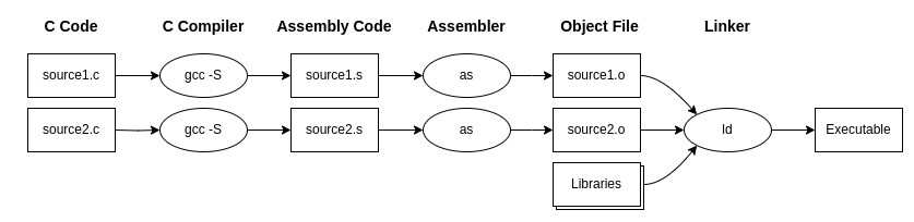
Figure 2.2.1: The compilation process of a program using GNU tools.
Compiling C Code to RISC-V Assembly Language
By default, compilers perform the entire compilation, assembly, and linking process when invoked from the command line.
To interrupt the compilation process after translating C code to assembly language, you must pass a flag to the compiler on the command line.
In the case of gcc and clang, this flag is -S.
The following command illustrates how to translate C code from the file prog.c to assembly language and save the result in the prog.s file.
clang -S prog.c -o prog.s
To test the above command, you can create a text file called prog.c and place the following content:
/* Program that returns the answer to the Ultimate Question of
 * Life, the Universe, and Everything */
int main(void) {
  return 42;
}
The command clang -S prog.c -o prog.s will produce code for the native machine's assembly language, i.e., for the machine running the compiler.
If you are running the compiler on a computer with an Intel or AMD processor, this means you will produce assembly language code for the x86 architecture family.
Since we are interested in producing code for RISC-V, we need to inform the compiler with special flags.
In the case of clang, we will use the flags --target=riscv32, -march=rv32g, and -mabi=ilp32d.
These flags configure the compiler to emit code for 32-bit RISC-V.
The code below illustrates the compilation of the code from the file prog.c to RISC-V assembly language:
clang --target=riscv32 -march=rv32g -mabi=ilp32d -mno-relax prog.c -S -o prog.s
You can check the contents of the prog.s file (produced by the above command) by opening it in your favorite text editor.
It is a text file and contains the same program you wrote in C, but transcribed into assembly language for the RISC-V RV32 architecture.
Note that assembly language refers to instructions (add, mv, etc.) and other elements specific to each type of processor and, consequently, is dependent on the processor's interface.
Note: In case your system runs on x86 or ARM based processors, if you compare the code produced for the native architecture and the code produced for RISC-V RV32, you will notice that the instructions generated by the compiler are quite different.
Assembling Programs in Assembly Language
The assembler converts the program in assembly language to machine language and stores it in an object file (.o).
To directly invoke the GNU assembler, you can use the as command, as illustrated below.
Note: By default, the as program assembles programs in assembly language for the native architecture.
Therefore, if you are running the as tool on a machine that does not have a RISC-V processor, it will generate an error if you try to assemble a RISC-V assembly program.
as prog.s -o prog.o
In this case, the assembler will store the result in the prog.o file.
Instead of directly calling the as command, you can use the compiler driver itself (gcc for GCC and clang for CLANG) to invoke the assembler.
To do this, simply use the command that invokes the compiler driver and pass the assembly language file as a parameter.
For example, with clang, you can execute:
clang --target=riscv32 -march=rv32g -mabi=ilp32d -mno-relax prog.s -c -o prog.o
In this example, we use the -c flag to instruct the compiler driver to stop the process after generating the object file.
If we didn't do this, the compiler driver would attempt to call the linker to generate the final executable.
You should not open the produced file (prog.o) in your text editor, as it is a binary file.
To analyze this file, you need special programs called "disassemblers" that interpret the file's content and convert its representation to human readable text.
These tools will be discussed in Chapter 2.6.
Generating the Executable from Object Files and Libraries
Once you have produced all the object files for your program, as illustrated in Figure 2.1, you need to combine all these files with libraries into a single executable file.
This process, called linking, is performed by the linker.
There are several tools that link object files with libraries.
The following example shows how we can use the ld.lld tool to combine the contents of the prog.o, module1.o, and module2.o files and produce the executable file prog.x.
ld.lld prog.o module1.o module2.o -o prog.x
If your program contains only one source file (e.g., prog.o), then simply pass this file to the linker, as illustrated below:
ld.lld prog.o -o prog.x
Disassembling object and executable files
Object files (.o) and executable files (.x) are binary files, and common text editors cannot display their contents in a readable form.
To analyze these files, you need special programs called "disassemblers", which interpret the file's contents and convert its representation to text.
You can use the GNU disassembler tool, objdump, or the llvm-objdump tool to disassemble the binary file and display its information in a textual format.
To do this, simply execute the command:
llvm-objdump -D prog.o
Compare the output produced by the disassembler (llvm-objdump) with the assembly language program file used during the assembly process (prog.s).
You'll notice that they are different, but share several common elements (e.g., lists of instructions to be executed by the processor).
Automating the Code Generation Process with Makefiles
The software development process involves multiple iterations of bug fixes and recompilations.
However, many of these projects have a large amount of source code files, and compiling all of them is a slow process.
The object files (.o) need to be linked again to form the new binary, but only the modified files need to be recompiled.
Therefore, it is important to have an automatic mechanism to recompile only the necessary files.
For this purpose, there is a specific type of script designed to automate software compilation.
The GNU Makefile is a widely used example in the GNU/Linux world.
To install it on a Debian-based distribution, you can run the following command:
sudo apt-get install build-essential
To create your own script that will instruct GNU Make to build your program, you should create a text file named Makefile, which should be in the same directory as the source code, containing rules for creating each file.
For example, you can create rules to specify how the .s file (in assembly language) is generated (using the clang compiler), how the object files .o (object code) are created (using the assembler), and so on.
Here is an example of some rules:
ola.s: ola.c
	clang --target=riscv32 -march=rv32g -mabi=ilp32d -mno-relax ola.c -S -o ola.s

ola.o: ola.s
	clang --target=riscv32 -march=rv32g -mabi=ilp32d -mno-relax ola.s -c -o ola.o
In this example, there are two rules named ola.o and ola.s.
The rule name should correspond to the file that is produced by the rule, followed by a colon ":".
For example, the rule that produces the ola.o file should be named "ola.o:".
The files required to produce the ola.o file should appear in a list (separated by spaces) after the colon ":" (in our case, ola.s is required to create ola.o).
Then, on the next line, you must use a tab (press the tab key) and type the command that will be executed in the shell to produce that file.
In our example, we call the clang compiler to translate a C file into assembly language, and in another rule, we call the assembler to transform an assembly language .s file into an object file .o.
Note that you can specify the name of another rule as the input file for a rule, and that rule will be invoked first to produce the required input file.
IMPORTANT: The script will not work if there is no tab (tab) before the commands "clang ..."!
Do not use spaces!
Additionally, note that some text editors insert spaces instead of tab characters when the tab key is pressed.
You can create multiple rules in the same Makefile.
To run the script, on the command line, type make rule-name. For example:
make ola.o
The make program will execute the commands associated with the ola.o rule described in the Makefile.
Note that the make program always reads the file named Makefile in the current directory and uses it as a script.
If you do not use this file name (Makefile with a capital "M"), the script will fail.
If you invoke the make command without any parameters, it will execute the first rule in the Makefile.
The links below provide more information about Makefiles:
Running Programs with the ALE Simulator
Running a program written in RISC-V assembly language requires either RISC-V hardware or a simulator. Since our computers do not have RISC-V processors, we will use the RISC-V ALE simulator to run programs compiled for RISC-V.
The RISC-V ALE simulator will run in your web browser (e.g., Chrome or Firefox). To do this, simply visit the page https://riscv-programming.org/ale/. Figure 3.0.1 illustrates the initial interface of the simulator.
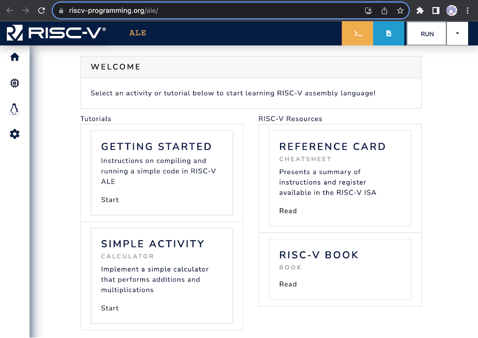
Figure 3.0.1: Initial simulator interface.
Overview of the Loading and Execution of Programs
Loading Files
The simulator has its own file system that enables storing multiple files.
To load files, you need to click on the file button  at the top right corner (left of RUN button), and select the files that you wish to load from your computer.
You can load executable files, source files or even data files to be accessed by your programs.
There is no directory structure, and existing files with the same name are automatically overwritten, in other words, if you load a file named prog.x more than once, just the last one will be kept.
Run: Compilation, Assembly, Linking and Execution of Programs
Once you have loaded your files, you can start your program execution. To do so, you must click on the RUN button (top right corner).
The simulator will identify the source files and, if necessary, perform the compiling, assembling and linking to get the executable. Finally, the simulator will invoke the executable and show the program's output (if there is any).
NOTE: The simulator stops the program's execution when (i) the program invokes the system call (syscall) exit, or (ii) when the execution finds invalid instructions. In the last case, the simulator may show error messages like "Error: Failed stop: 64 consecutive illegal instructions: 0". This is expected in programs that do not call the exit syscall, as the processor doesn't know where the program ends and will continue to execute instructions consecutively, until it finds invalid instructions.
C programs without LibC
Programs written in C are usually linked to the C standard library and with object files that contain support routines to the application's execution.
These routines, initialize the C library's data structures, organize the parameters to the main function (_start) and, after returning from the main function, invoke the operating system to signal the end of the application (function exit).
_start function and exit syscall
Besides linking the code from multiple object files (.o), the linker must register the address of the entry function of the program on the header of the executable file so that the operating system's loader knows where to start the execution of the program once it starts.
By default, in C and C++, the program's entry point is defined by the function called _start.
This is a short function that invokes the function main and after main returns, it invokes the exit syscall to inform the operating system that the program has finished.
When generating the executable files, C and C++ compilers link an object file that has the implementation of this function. However, the RISC-V compiler used here doesn't link to such file (nor LibC), this way, it is necessary to include an implementation of the function.
The following code shows possible implementations to the function exit and the function _start.
In this example, the function exit consists of a sequence of instructions in assembly language that copies the value of function parameter (code) to the register a0, puts the value 93 on register a7 and generates a software interrupt (ecall instruction).
The software interrupt redirects the execution flow to the operating system, which will use the value on register a7 to determine which syscall was requested and the value on register a0 as a parameter to the call.
void exit(int code)
{
  __asm__ __volatile__(
    "mv a0, %0           # return code\n"
    "li a7, 93           # syscall exit (93) \n"
    "ecall"
    :             // Output list
    :"r"(code)    // Input list
    : "a0", "a7"
  );
}

void _start()
{
  int ret_code = main();
  exit(ret_code);
}
The _start function code simply calls the main function, which is implemented by the user, and, after main's return, invokes the exit function passing the main return value as a parameter.
You can copy and paste these two functions on your C programs that will be executed on the ALE simulator.
Alternatively, you can put them in a file called start.c and compile/assemble/link the file with your program.
read and write syscalls
In general, programs that execute in computer systems that have an operating system don't have direct access to the system's peripherals (e.g., monitor, keyboard, mouse, ...), in other words, that can't interact directly with these devices. In this case, all interactions with these devices are done via system calls (syscalls).
The organization of the Linux operating system is strongly based on the concept of files. In this context, each file is identified by a path and a name (e.g., /home/students/john/prog.c). In addition to that, when a file is opened by a program, the operating system associates this file with a file descriptor and returns this file descriptor to the program. The file descriptor is an integer that must be provided by the program every time it requests the operating system to perform an operation with the file (e.g., write or read of data). In short, to write to (or read from) a file, the program must:
- Invoke the operating system with the open syscall to open the file. This syscall will open the file and return an integer that corresponds to the file descriptor of the opened file.
- Invoke the write or read syscall passing as argument the file descriptor of the file and a buffer to write or read data; and, finally
- Invoke the operating system with the close syscall to close the file.
There are three special file descriptors that are always available and don't have to be opened or closed: STDIN, STDOUT and STDERR.
The values of the file descriptors STDIN, STDOUT and STDERR are 0, 1 e 2, respectively.
These file descriptors correspond to the standard input, standard output and error output of the program. When the program writes to standard output or error output, the operating system shows what was written on the terminal; where the program is being executed. In case the program reads from standard input, the operating system (i) waits until the user types something in the standard input and press ENTER, and (ii) returns to the program what was typed in the terminal.
The following code shows the implementation of a function in C that contains code in RISC-V assembly language to invoke the syscall read. This function contains a set of RISC-V instructions that adjust the parameters and invoke the operating system to perform the read operation through the read syscall.
/* read
 * Parameters:
 *  __fd:  file descriptor of the file to be read.
 *  __buf: buffer to store the data read.
 *  __n:   maximum amount of bytes to be read.
 * Return:
 *  Number of bytes read.
 */
int read(int __fd, const void *__buf, int __n)
{
    int ret_val;
  __asm__ __volatile__(
    "mv a0, %1           # file descriptor\n"
    "mv a1, %2           # buffer \n"
    "mv a2, %3           # size \n"
    "li a7, 63           # syscall read code (63) \n"
    "ecall               # invoke syscall \n"
    "mv %0, a0           # move return value to ret_val\n"
    : "=r"(ret_val)                   // Output list
    : "r"(__fd), "r"(__buf), "r"(__n) // Input list
    : "a0", "a1", "a2", "a7"
  );
  return ret_val;
}
As you don't have access to the C standard library, you can use the function above to perform read operations from the standard input.
To do so, just call the function read to the file descriptor of value 0.
To use it, you must allocate a buffer, that can be a global variable, like the example below.
Note that the global variable (input_buffer) is an array with 10 characters, a 10 byte array.
After reading the data, the read function writes the read bytes to the provided buffer and returns the amount of bytes read.
The last parameter of the read function indicates the maximum amount of bytes that must be read.
In case the amount of bytes that can be read is greater than this value, the read function just writes the maximum amount of bytes (10 in the example below) on the input buffer and returns.
The remaining bytes are stored in an internal buffer of the operating system and are returned when the read function is called again.
/* Buffer to store the data read */
char input_buffer[10];

int main()
{
  /* fd = 0 : reads from standard input (STDIN) */
  int n = read(0, (void*) input_buffer, 10);
  /* … */
  return 0;
}
The following code shows a possible C implementation of the function write. This C function contains a code in RISC-V assembly language to invoke the system call (syscall) write. It invokes the operating system to write __n bytes from the buffer __buf on the file (or device) indicated by the file descriptor, parameter __fd. When __fd = 1, this function writes to the standard output (STDOUT).
/* write
 * Parameters:
 *  __fd:  files descriptor where that will be written.
 *  __buf: buffer with data to be written.
 *  __n:   amount of bytes to be written.
 * Return:
 *  Number of bytes effectively written.
 */
void write(int __fd, const void *__buf, int __n)
{
  __asm__ __volatile__(
    "mv a0, %0           # file descriptor\n"
    "mv a1, %1           # buffer \n"
    "mv a2, %2           # size \n"
    "li a7, 64           # syscall write (64) \n"
    "ecall"
    :   // Output list
    :"r"(__fd), "r"(__buf), "r"(__n)    // Input list
    : "a0", "a1", "a2", "a7"
  );
}
Again, as you don't have access to the C standard library, you can use the function above to write to the standard output of the program, in other words, the terminal where your program was executed. To do so, just call the function write to the file descriptor 1. The code below shows an example where the write function is called to show a string on the output terminal.
/* Allocates a global string with 5 bytes.
 *   Note: the break line character, \n is encoded
 *       with a single byte */
char my_string[] = "1969\n";

int main()
{
  /* Prints the first 5 characters from the string on
   * the standard output, in other words, 1, 9, 6, 9 and break line. */
  write(1, my_string, 5);

  return 0;
}
The ALE simulator expects a break line character (\n) to print the content written to the standard output on the terminal.
This way, you must add a break line character at the end of your buffer or call the function write again with a string that has the break line character.
The example above shows a program that prints a string with 5 characters ending with a break line.
Complete example
The following program combines all the parts discussed above and implements a program that reads a string from the standard input, makes specific modifications to the string, and writes the modified string to the standard output.
int read(int __fd, const void *__buf, int __n){
    int ret_val;
  __asm__ __volatile__(
    "mv a0, %1           # file descriptor\n"
    "mv a1, %2           # buffer \n"
    "mv a2, %3           # size \n"
    "li a7, 63           # syscall write code (63) \n"
    "ecall               # invoke syscall \n"
    "mv %0, a0           # move return value to ret_val\n"
    : "=r"(ret_val)  // Output list
    : "r"(__fd), "r"(__buf), "r"(__n)    // Input list
    : "a0", "a1", "a2", "a7"
  );
  return ret_val;
}

void write(int __fd, const void *__buf, int __n)
{
  __asm__ __volatile__(
    "mv a0, %0           # file descriptor\n"
    "mv a1, %1           # buffer \n"
    "mv a2, %2           # size \n"
    "li a7, 64           # syscall write (64) \n"
    "ecall"
    :   // Output list
    :"r"(__fd), "r"(__buf), "r"(__n)    // Input list
    : "a0", "a1", "a2", "a7"
  );
}

void exit(int code)
{
  __asm__ __volatile__(
    "mv a0, %0           # return code\n"
    "li a7, 93           # syscall exit (64) \n"
    "ecall"
    :   // Output list
    :"r"(code)    // Input list
    : "a0", "a7"
  );
}

void _start()
{
  int ret_code = main();
  exit(ret_code);
}

#define STDIN_FD  0
#define STDOUT_FD 1

/* Buffer to store the data read */
char input_buffer[10];


int main()
{
  /* Reads a string from standard input */
  int n = read(STDIN_FD, (void*) buffer, 10);

  /* Modifies the string */

  /* Replaces the first character with the letter M */
  buffer[0]   = 'M';

  /* Replaces the last character (n-1) with an exclamation mark and
   * Adds a newline character to the buffer immediately after the string
   * NOTE: In the ALE simulator, if the input is typed in the terminal
   * and followed by pressing Enter, the last character will be a '\n'.
   */
  buffer[n-1]   = '!';
  buffer[n]     = '\n';

  /* Prints the read string and the two added characters
   * in standard output. */
  write(STDOUT_FD, (void*) buffer, n+2);

  return 0;
}
During its execution, the program invokes the operating system to read a string from the standard input, i.e., from the terminal displayed by the simulator. The operating system, in turn, waits until the user types something in the terminal and presses ENTER. It then stores the typed string in the buffer provided by the program and returns the number of bytes read. Figure 3.1.1 shows the simulator's terminal. In this case, to enter data into the standard input, simply click on the terminal window, type the text, and press ENTER.
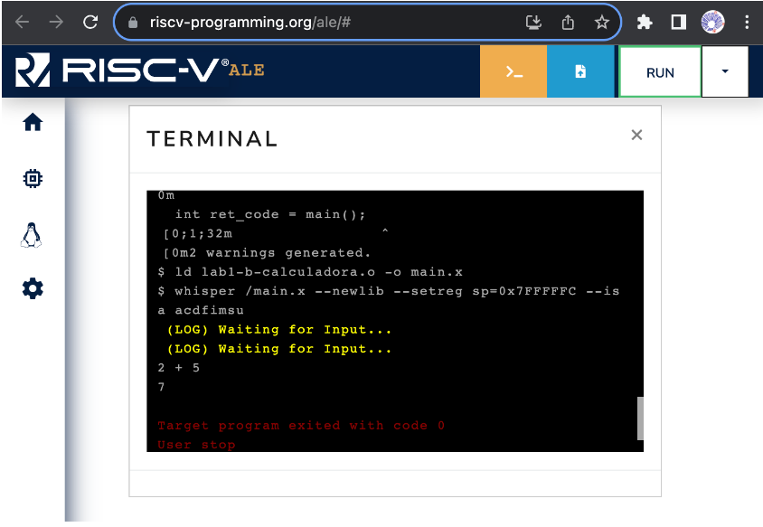
Figure 3.1.1: Simulator terminal.
Enabling System Calls in ALE
The ALE simulator is configurable and allows users to run applications with or without system call (syscall) support. To enable or disable syscalls, or to choose which syscalls are available, you can click on the Operating System menu (penguin icon) and adjust the options, as illustrated in Figure 3.1.2.
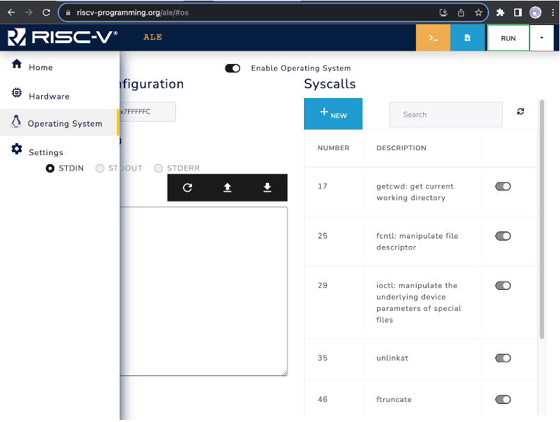
Figure 3.1.2: Adjusting System Call Options in ALE.
Execution with the Assistant
The ALE simulator supports the use of execution assistants that automatically run one or more tests with the loaded code and produce a report with information about the submitted code and the results of the tests.
Overview of the Execution Assistant
The assistant is encoded in the URL that points to the simulator. This link, for example, contains the address of the simulator and the code for an assistant that is loaded when the simulator is opened. You can click the link and inspect the menu that appears after clicking the arrow next to the RUN button. Figure 3.2.1 illustrates accessing the debugging assistant.
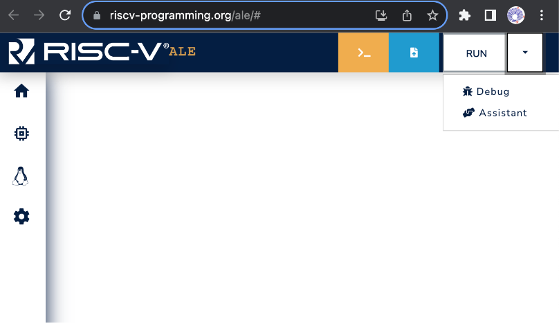
Figure 3.2.1: Accessing the Assistant in the ALE Simulator.
When you click on the Assistant button, the simulator will open a window with information about the debugging assistant. The information provided depends on the specific assistant. Figure 3.2.2 shows the assistant loaded from the link above. Note that it includes the RUN TESTS button, which is used to start the tests.
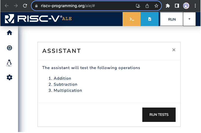
Figure 3.2.2: Example of a window with assistant information. In this case, the assistant contains three tests: 1. Addition, 2. Subtraction and 3. Multiplication.
Running a program with the execution assistant
To test your program with the debugging assistant, simply open the simulator with a link that includes an assistant (such as this one), load your program into the simulator (see Chapter 3.1), and click the RUN TESTS button in the assistant's window. Figure 3.2.3 shows an example where the assistant is running tests with the loaded program. In this case, the program produced the correct results for tests 1 (Addition) and 2 (Subtraction) and is currently being executed with test 3.
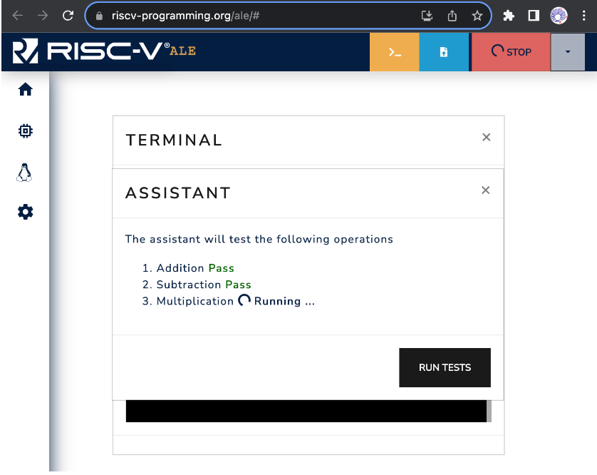
Figure 3.2.3:Example of test execution with the assistant.
Some assistants provide an option to download a report with the test results at the end of the testing process. Figure 3.2.4 shows an example where, after the tests are completed, the assistant displays the score and provides a link to retrieve the report.
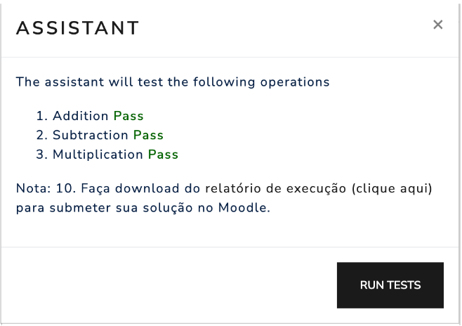
Figure 3.2.4: Example of test execution.
Debugging Code with ALE
The ALE simulator features an interactive interface that allows users to control program execution and inspect the values of registers and memory. This interface is very similar to the GDB debugger's interface, enabling users to debug their code's execution.
Overview of the interactive interface
To enable the interactive execution interface, simply click the arrow next to the RUN button and select the "Debug" option, as illustrated in Figure 3.3.1.
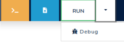
Figure 3.3.1: Select the "Debug" option.
Once you clicked on the Debug option, the simulator will open an interactive terminal where you can enter commands to control execution and/or inspect the state of the memory and registers of the RISC-V processor. Figure 3.3.2 shows an interactive terminal.
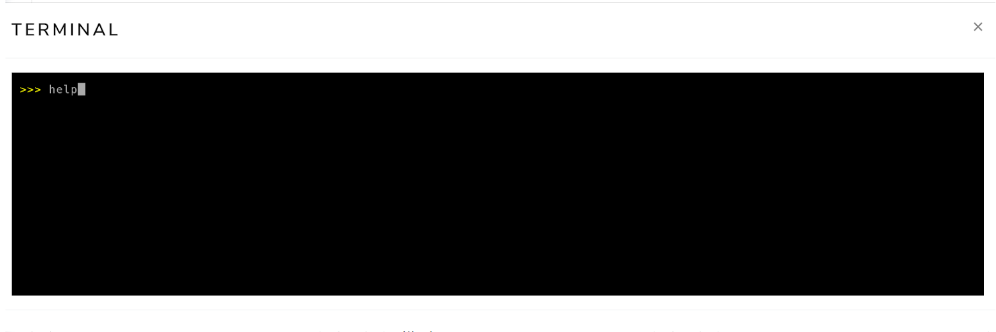
Figure 3.3.2: Interactive terminal in the ALE simulator.
Debugging commands
To see the complete list of available commands in debug mode, you can run the help command in the interactive terminal.
Simply type help in the interactive terminal and press ENTER.
A portion of the command list displayed by the help command is shown below.
run
  Run till interrupted.
until <address>
  Run until address or interrupted.
step [<n>]
  Execute n instructions (1 if n is missing).
peek <res> <addr>
  Print value of resource res (one of r, f, c, m) and address addr.
  For memory (m) up to 2 addresses may be provided to define a range
  of memory locations to be printed.
  examples: peek r x1   peek c mtval   peek m 0x4096
peek pc
  Print value of the program counter.
peek all
  Print value of all non-memory resources
poke res addr value
  Set value of resource res (one of r, c or m) and address addr
  Examples: poke r x1 0xff  poke c 0x4096 0xabcd
symbols
  List all the symbols in the loaded ELF file(s).
quit
  Terminate the simulator
The following table summarizes the main commands available in the interactive interface of the ALE simulator:
| Command | Description |
|---|---|
symbols | Shows the address of symbols (e.g., _start, loop, end, result) of the program. The address is displayed in hexadecimal format (e.g., 0x11180). |
until <address> | Executes instructions of the program until a certain address. The address must be provided in hexadecimal format (e.g., 0x11180). |
step [n=1] | Executes the next n instructions |
peek r <register> | Displays the value stored in register peek r x1 or peek r mtval). The value is shown in hexadecimal format. The command peek r all shows the value of all registers. |
peek m <address> | Displays the value stored in the memory word at address <address>. The value is shown in hexadecimal format. |
poke r <register> <value> | Modifies the content of register <register> with the value <value>. For example, the command poke r x1 0xff stores the value 0xff in register x1. |
poke m <address> <value> | Modifies the content of the memory location associated with address <address> with the value <value>. For example, the command poke m 0x800 0xfe writes the value 0xfe to the memory location associated with address 0x800. |
run | Executes the program until it terminates through a system call exit or encounters invalid instructions. |
Interactive execution example
In this section, we will show an example of interactive execution with the ALE simulator.
For this, we will use the program simple-debug.s, as follows:
.globl _start

_start:
  li x11, 21          # loads the value 21 into register x11
  li x12, 21          # loads the value 21 into register x12
  add x10, x11, x12   # adds the contents of registers x11 and x12 and
                      # stores the result in register x10
  li a7, 93           # loads the value 93 into register a7
  ecall               # generates a software interrupt
This program loads the value 21 into registers x11 and x12, performs the addition of these values, and stores the result in register x10.
Finally, it invokes the exit syscall.
To do this, the program loads the value 93 into register a7 and generates a software interrupt by executing the ecall instruction.
The first step is to load the simple-debug.s file into the simulator.
To do this, simply use the file upload button (blue), as discussed in Chapter 3.1.
Next, you should open the interactive execution terminal by clicking on the debug button, as presented in Chapter 3.3.1.
Once you open the interactive execution terminal, you should see messages indicating that the simple-debug.s program has been assembled and its execution has begun in interactive mode, as illustrated in Figure 3.3.3.
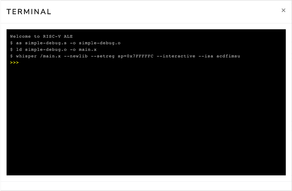
Figure 3.3.3: Interactive terminal opened right after loading the file simple-debug.s.
Now, simply click on the terminal and type commands to interact with the simulator. To illustrate this procedure, we will execute the following sequence of commands:
peek r x11
step
peek r x11
Figure 3.3.4 shows the interactive terminal after executing the commands peek r x11, step, and peek r x11.
The first command shows that the content of register x11 is zero (0x00000000).
The second command advances the execution of the program by one instruction.
Note that the simulator displays the instruction addi x11, x0, 0x15, which adds the content of register x0 (which is always zero1) to the constant 0x15 (i.e., 21 in decimal), and stores the result in register x11.
In our assembly language program, we had the instruction li x11, 21 (load immediate), which loads the value 21 into register x11.
The load immediate instruction is a pseudo-instruction (it does not exist in the architecture) and is usually transformed by the assembler into an addi instruction.
Finally, the third command inspects the content of register x11.
Note that this time it contains the value 21 (0x00000015).
Also note that, the interactive terminal outputs some informations regarding the instruction that was executed in the format:
- Inst Num: number of the machine instruction that was executed
- Mem Addr: memory address of the instruction that was executed.
- Inst Code: code of the instruction that was executed.
- Inst Type: can be either
rif the instruction uses only register ormif there is a memory access (store or load). - Val: value stored in the
rdregister for instructions of typeror stored in the memory position accessed for typeminstructions. - Mnemonic: assembly mnemonic of the executed instruction.
The second occurrence of the instruction #1 can be ignored.
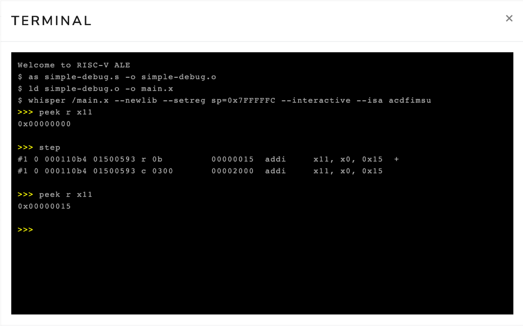
Figure 3.3.4: Interactive terminal after executing the commands peek r x11, step and peek r x11.
Now, we will execute the following sequence of commands to advance our program to the end, that is, until we invoke the exit syscall.
step
step
step
peek r x10
step
The first three step commands advance the execution to the ecall instruction, executing the instructions li x12, 21, add x10, x11, x12, and li a7, 93.
The next command displays the content of register x10.
Finally, the last command advances the execution, causing the simulator to execute the ecall instruction.
Figure 3.3.5 shows the interactive terminal after executing these commands.
Notice that, again, the li instructions from the source program were encoded as addi instructions.
Also, the value of register x10 has been changed to 0x2a (42 in decimal).
Finally, note that the program ended with code 42.
This occurred because we passed the value 422 as a parameter to the exit syscall.
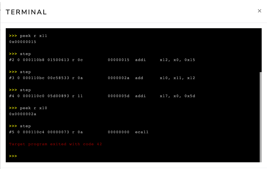
Figure 3.3.5: Interactive terminal after executing the commands step, step, step, peek r x10, step.
In the example above, we used the step command to advance the program execution instruction by instruction.
However, in many situations, it is useful to advance the simulation automatically to a certain point in the program.
To do this, you can use the until command.
This command takes as a parameter the address of the instruction where you want to advance to.
In Figure 3.3.5, we see that the ecall instruction is at address 0x000110c4.
Therefore, if we wanted to advance execution to this point, we could execute the command until 0x000110c4.
Figure 3.3.6 shows the interactive terminal after executing the command until 0x000110c4.
Note that the simulator displayed the execution of the first four instructions of the program.
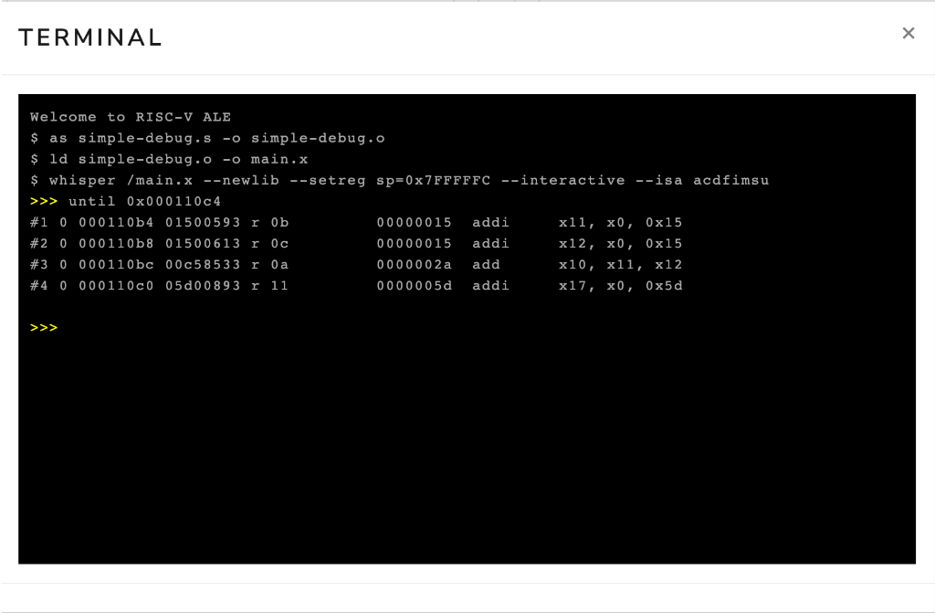
Figure 3.3.6: Interactive terminal after executing the command until 0x000110c4.
Identifying the address associated with instructions
As seen above, you can use the address of an instruction to advance execution to the desired instruction. To do this, you need the address of the instruction. The most direct way to obtain the address of an instruction is by using the disassembler. To do this, you need to disassemble the final executable file. Chapter 2.6 discusses how to use the disassembler.
Another way to identify the address of an instruction is from the label that precedes it in the code.
In our example, the address of the first instruction corresponds to the address of the label _start.
To identify the addresses associated with the labels in your program, simply execute the symbols command.
If the instruction of interest does not have a preceding label, you can add a new label (with a name different from other labels in the program).
This label will not affect code generation, i.e, the set of emitted instructions will remain the same.
The following code snippet shows the simple-debug-2.s program modified with a label to facilitate the identification of the address of the instruction li a7, 93.
When you load this program into the simulator and execute the symbols command in the interactive terminal, you will see the addresses associated with the symbols _start and before_exit.
.globl _start
_start:
  li x11, 21          # loads the value 21 into register x11
  li x12, 21          # loads the value 21 into register x12
  add x10, x11, x12   # adds the contents of registers x11 and x12 and
                      # stores the result in register x10
before_exit:
  li a7, 93           # loads the value 93 into register a7
  ecall               # generates a software interrupt
Terminal IO in Debug Mode
When in debug mode, there are two ways in which you can provide an input to your program in case a read syscall is called.
The first one is to use the Standard IO textbox to load the input, and the second is to use the write-stdin command followed by the input string on the terminal input.
These two ways are demonstrated with images below.
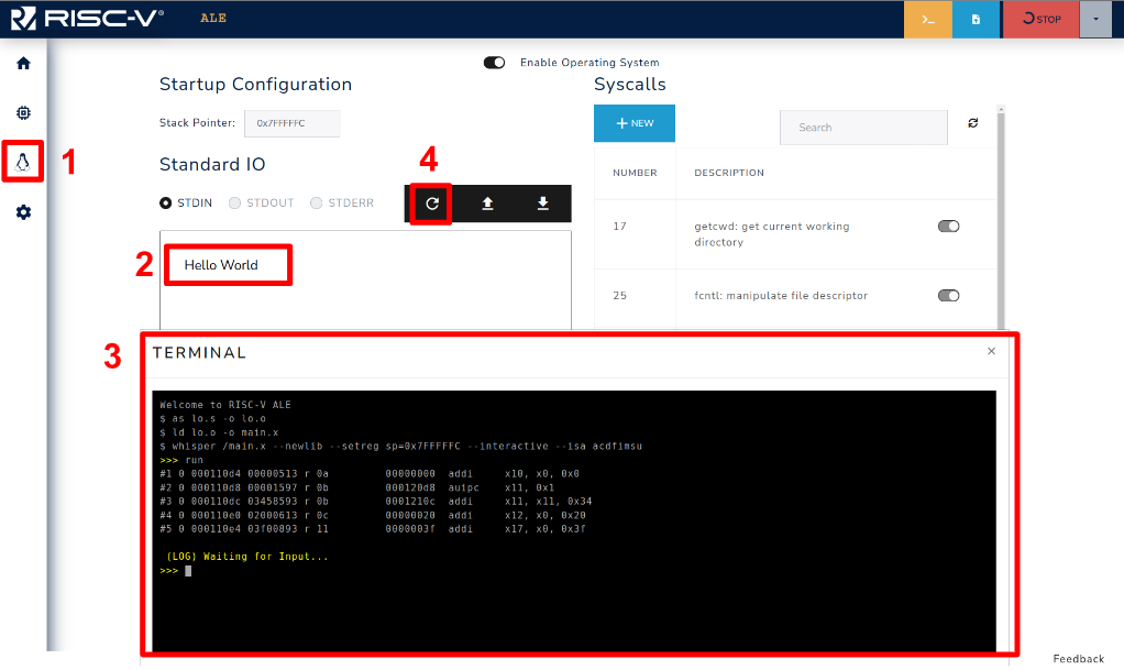
Figure 3.3.7: Loading input using the OS Standard IO.
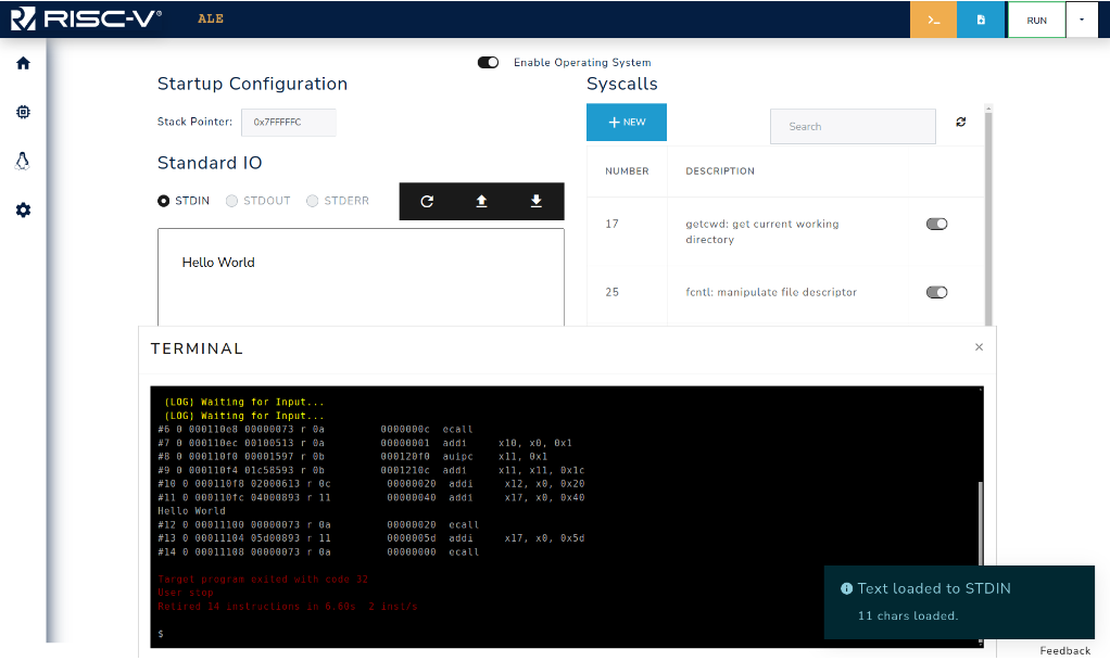
Figure 3.3.8: Simulator after loading the input.
Figure 3.3.7 shows how to use the OS to load the input that will be read by the program. First go to the OS tab (1) and write your input on the textbox (2), then run your code in debug mode until the point where the input is expected (3). Finally, load the input by clicking on the button (4). Figure 3.3.8 presents the terminal after loading the input, as the code just reads an input and writes it to STDOUT you can see that the input (Hello World) is printed on the screen and the program exits. The input can also be loaded prior to the program execution (step 4 before 3).
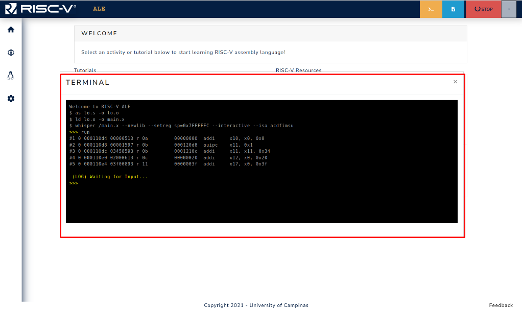
Figure 3.3.9: Blocked program waiting for input in Debug Mode.
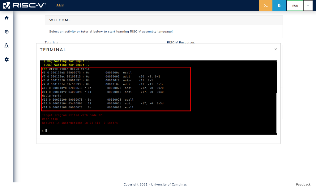
Figure 3.3.10: Command write-stdin is used to set input in debug mode.
The other way that can be used to provide input to your program is via the write-stdin command.
When the program reaches a point where the read syscall is invoked, it blocks waiting for the input, and the user can use the terminal as shown in Figure 3.3.9.
Figure 3.3.10 shows the write-stdin followed by the input string being used, and after the command the program continues its execution using the provided input.
In RISC-V, register x0 always holds the fixed value of zero.
Even if an instruction tries to write something to this register, the value zero will be preserved in the register.
The exit syscall expects a parameter, which is the exit code, in register a0 (which is an alias for register x10).
Although the object file contains the same instructions as the final executable file, the address of the instructions is usually modified by the linking process. Therefore, you should use the final executable file when you want to identify the addresses of the instructions.
Enabling and Interacting with Peripherals
The ALE simulator features a set of peripherals that can be enabled to perform a set of tasks, such as controlling a car in a 3D environment, playing a song with a MIDI player, or displaying an image on a canvas.
Overview of Peripherals and how they are connected to the system
Peripherals are input/output devices that are connected to the computer using a bus. The interaction between the CPU and such devices can be performed either by port-mapped IO or Memory-mapped IO. The former uses special instructions to access the peripheral's register and internal memory, while the latter uses some memory regions in order to perform I/O operations with the peripheral device. More information about this topic can be found in Chapter 8 of the book An Introduction to Assembly Programming with RISC-V.
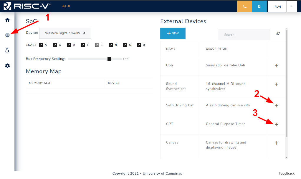
Figure 3.4.1: Steps to enable external devices.
In the ALE simulator, the peripherals are accessed with MMIO, and the region of the memory
that is reserved to each peripheral is set when the peripheral is enabled on the simulator
Figure 3.4.1 shows how to access the devices tab of the simulator (1), and a device can be enabled by clicking on the + symbol next to the device description (2,3).
The result of the actions performed in Figure 3.4.1 can be seen in Figure 3.4.2.
Two devices were enabled on the simulator: self_driving_car.js (car) and general_purpose_timer.js (GPT).
The car device is mapped to the MMIO region 0xFFFF0100 - 0xFFFF0300, and GPT is mapped to the MMIO region 0xFFFF0300 - 0xFFFF0500, which means that the base address for the car and GPT will be 0xFFFF0100 and 0xFFFF0300, respectively.
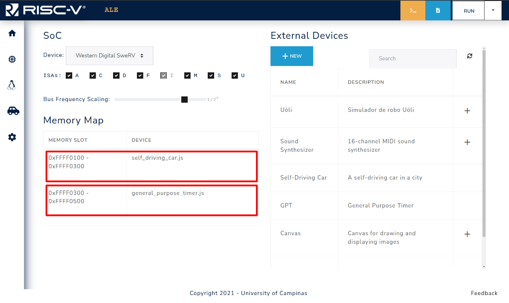
Figure 3.4.2: MMIO region (Memory slot) assigned to each enabled device.
NOTE: It is important to notice that the memory slot, and hence the peripheral base address, may change according to the order they are inserted into the simulator. You may want to take this into account when adding peripherals to your system.
Accessing Peripherals with MMIO
Each peripheral uses its memory slot in its own manner, Chapter 5 provides each peripheral's usage of its memory slot. The interaction with the peripheral is done via reads/writes from/to memory. The example below shows an example on how to get GPS readings from the Self-Driving Car peripheral using the base address from Figure 3.4.2.
.globl _start
.set CAR_BASE_ADDRESS, 0xFFFF0100

_start:
  lw t0, CAR_BASE_ADDRESS # loads the value associated with the symbol
                          # CAR_BASE_ADDRESS (0xFFFF0100) in register t0
  li t1, 1                # loads the value 1 into register t1
  sb t1, 0(t0)            # stores the value 1 in car's
                          # base address+0x00 to trigger GPS reading
  busy_wait_loop:
    lb t1, 0(t0)            # loads value from base address+0x00
    bnez t1, busy_wait_loop # checks if value is 0,
                            # indicating that GPS reading is over
  lw t1, 4(t0)            # loads Euler angle X in register t1
  lw t2, 8(t0)            # loads Euler angle Y in register t2
  lw t3, 12(t0)           # loads Euler angle Z in register t3
  lw t4, 16(t0)           # loads X-axis position in register t4
  lw t5, 20(t0)           # loads Y-axis position in register t5
  lw t6, 24(t0)           # loads Z-axis position in register t6
  # ...

  # Invoke the exit syscall
  li a7, 93           # Loads the syscall ID (93) into register a7
  ecall               # Generates a software interrupt
The example above illustrates the process of reading the GPS coordinates from the car GPS.
First the base address of the car peripheral is loaded in register t0, then we set the byte in base address to 1, signaling the car to read the GPS coordinates.
Since it takes some time for the car device to perform the reading and update the values, we do what is called busy waiting, by checking the memory address that indicates if the reading is complete in a loop.
When the value is set to 0, the execution flow gets out of the loop, and proceeds to load the GPS coordinates that were read, available at addresses base+0x04, base+0x08, base+0x0C, base+0x10, base+0x14, and base+0x18 into registers t1, t2, t3, t4, t5, and t6, respectively.
Peripherals in ALE
This chapter presents how the peripherals use their respective memory regions, relevant to peripheral interactions via MMIO.
Canvas
| Address | Size | Description |
|---|---|---|
base+0x00 | byte | Storing 1 triggers the canvas to write an array of up to 504 bytes representing up to 126 pixels to the screen. The register is set to 0 when writing is completed. |
base+0x02 | half | Array size (in bytes). |
base+0x04 | word | The initial position to write the array on the canvas. The canvas is represented as a 512x512x4-byte one-dimensional array representing 512x512 pixels. |
base+0x08tobase+0x200 | word | 504-byte array representing up to 126 pixels. Each pixel takes 4 bytes, one byte for each value: Red, Green, Blue, and Alpha (in this order). |
General Purpose Timer
| Address | Size | Description |
|---|---|---|
base+0x00 | byte | Storing 1 triggers the GPT device to start reading the current system time. The register is set to 0 when the reading is completed. |
base+0x04 | word | Stores the time (in milliseconds) at the moment of the last reading by the GPT. |
base+0x08 | word | Storing v > 0 programs the GPT to generate an external interruption after v milliseconds. It also sets this register to 0 after v milliseconds (immediately before generating the interruption). |
MIDI Synthesizer
| Address | Size | Description |
|---|---|---|
base+0x00 | byte | Storing ch ≥ 0 triggers the synthesizer to start playing a MIDI note in the channel ch. |
base+0x02 | short | Instrument ID. |
base+0x04 | byte | Note. |
base+0x05 | byte | Note velocity. |
base+0x06 | short | Note duration. |
Self Driving Car
| Address | Size | Description |
|---|---|---|
base+0x00 | byte | Storing 1 triggers the GPS device to start reading the coordinates and rotation of the car. The register is set to 0 when the reading is completed. |
base+0x01 | byte | Storing 1 triggers the Line Camera device to capture an image. The register is set to 0 when the capture is completed. |
base+0x02 | byte | Storing 1 triggers the Ultrasonic Sensor device to measure the distance in front of the car. The register is set to 0 when the measurement is completed. |
base+0x04 | word | Stores the Euler angle X of the car rotation at the moment of the last reading by the GPS. |
base+0x08 | word | Stores the Euler angle Y of the car rotation at the moment of the last reading by the GPS. |
base+0x0C | word | Stores the Euler angle Z of the car rotation at the moment of the last reading by the GPS. |
base+0x10 | word | Stores the X-axis of the car position at the moment of the last reading by the GPS. |
base+0x14 | word | Stores the Y-axis of the car position at the moment of the last reading by the GPS. |
base+0x18 | word | Stores the Z-axis of the car position at the moment of the last reading by the GPS. |
base+0x1C | word | Stores the distance (in centimeters) between the Ultrasonic sensor and the nearest obstacle. Returns -1 if there’s no obstacle within 20m. |
base+0x20 | byte | Sets the steering wheel direction. Negative values indicate steering to the left, positive values indicate steering to the right. |
base+0x21 | byte | Sets the engine direction.1: forward.0: off.-1: backward. |
base+0x22 | byte | Sets the hand break. (1 = enabled) |
base+0x24 | 256-byte array | Stores the image captured by the Line Camera. Each byte represents the luminance of a pixel. |
Serial Port
The serial port is connected to the terminal (stdout and stdin).
| Address | Size | Description |
|---|---|---|
base+0x00 | byte | Storing 1 triggers the serial port to write (to the stdout) the byte stored at base+0x01. The register is set to 0 when writing is completed. |
base+0x01 | byte | Byte to be written. ID |
base+0x02 | byte | Storing 1 triggers the serial port to read (from the stdin) a byte and store it at base+0x03. The register is set to 0 when reading is completed. |
base+0x03 | byte | Byte read. NULL (0) when stdin is empty. |
Developing New Execution Assistants
The ALE simulator provides an Execution Assistant class that is embedded in the simulator URL, and allows a programmatic interaction with the simulator capabilities, relevant when creating grading scripts with test cases. This chapter provides an overview of the Assistant class and how to develop and use new ones.
Overview of How an Assistant Works
As explained in Chapter 1, the ALE simulator is a web-based simulator that is a mix of JavaScript code, WebAssembly artefacts and Unity Assets (for some peripherals). One of the classes that composes the simulator architecture is the Assistant Script component.
This component’s class can be extended to customize the assistant modal window, like adding buttons to perform certain actions, add functions that must be executed when the page is initially loaded, and also test cases that will be executed when the RUN TESTS button is clicked.
An example of an assistant script is shown below.
// Import assistant and logging modules
import { UI_Helper, Assistant_Script } from "./modules/assistant.js";
import { LocalReport } from "./modules/connection.js";

class Ex2_2 extends Assistant_Script {
  constructor() {
    super();
    this.ui = new UI_Helper("Exercise 2.2: Simple Symbol Calculator");
    let report = new LocalReport();
    this.connections.push(report);

    // Enable syscalls and set the program stack
    this.predefined_args = [
      "--newlib",
      "--setreg",
      "sp=0x7FFFFFC",
      "--isa",
      "acdfimsu",
    ];

    this.ui.add_test(
      "Compilation",
      (_) => {
        report.restart();
        return this.generic_compile_test()();
      },
      { fail_early: true }
    );

    // Add fixed tests
    let test_id = 1;
    this.ui.add_test(
      `Test ${test_id++} (question) - Add`,
      this.simple_equality_test(`2 + 3\n`, `5\n`, {
        compare_function: (a, b) => a.trim() == b.trim(),
      })
    );
    this.ui.add_test(
      `Test ${test_id++} (question) - Sub`,
      this.simple_equality_test(`7 - 7\n`, `0\n`, {
        compare_function: (a, b) => a.trim() == b.trim(),
      })
    );
    this.ui.add_test(
      `Test ${test_id++} (question) - Mul`,
      this.simple_equality_test(`4 * 2\n`, `8\n`, {
        compare_function: (a, b) => a.trim() == b.trim(),
      })
    );

    for (let i = 0; i < 3; i++) {
      let a = this.randint(0, 9);
      let b = this.randint(0, 9 - a);
      this.ui.add_test(
        `Test ${test_id++} - Add`,
        this.simple_equality_test(`${a} + ${b}\n`, `${a + b}\n`, {
          compare_function: (a, b) => a.trim() == b.trim(),
        })
      );
      a = this.randint(0, 9);
      b = this.randint(0, a);
      this.ui.add_test(
        `Test ${test_id++} - Sub`,
        this.simple_equality_test(`${a} - ${b}\n`, `${a - b}\n`, {
          compare_function: (a, b) => a.trim() == b.trim(),
        })
      );
      a = this.randint(0, 3);
      b = this.randint(0, 3);
      this.ui.add_test(
        `Test ${test_id++} - Mul`,
        this.simple_equality_test(`${a} * ${b}\n`, `${a * b}\n`, {
          compare_function: (a, b) => a.trim() == b.trim(),
        })
      );
    }

    this.ui.final_result = (_) => {
      report.report["test_results"] = this.ui.test_results;
      let grade = 0;
      if (this.ui.test_results[0] != 0) {
        let n_tests = this.ui.test_results.length;
        for (let i = 1; i < n_tests; i++) {
          grade += this.ui.test_results[i];
        }
        grade = (grade * 10) / (n_tests - 1);
      }
      report.report["final_grade"] = grade;
      window.parent.postMessage({
        comment: this.ui.test_results,
        grade: grade,
        finish_test: true,
      });
      let blob = report.generate_report();
      return `Grade: ${grade}. Download your test report from Assistant execution report <a href=${window.URL.createObjectURL(
        blob
      )} download="ex2_2.report">(click here)</a>.`;
    };
  }

  randint(min, max) {
    return Math.floor(Math.random() * (max - min) + min);
  }
}

new Ex2_2();
In order to encode this assistant in an URL, the flow shown in Figure 5.1.1 needs to be followed.
First you need to go to the Settings tab (1), load the assistant file (2), and then generate the link (3).
The link can then be copied using the COPY TO CLIPBOARD BUTTON (4).
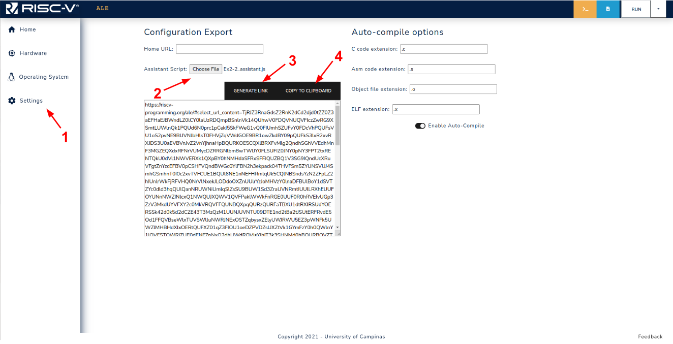
Figure 5.1.1: Assistant link generation workflow.
When opening the link in a new tab, the assistant modal will have the test cases loaded, as shown in Figure 5.1.2.
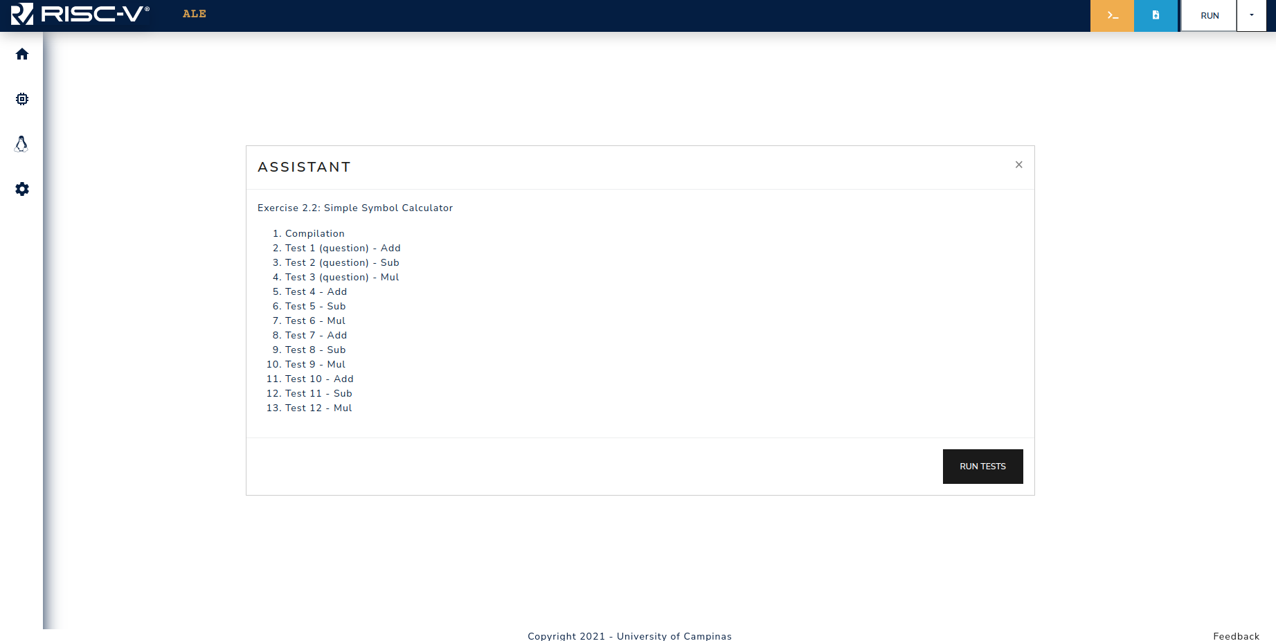
Figure 5.1.2: Assistant modal when opening the embedded link.
When generating such links, one additional thing that can be done is attaching active peripherals to the link. For instance, if the tests to be performed use a given peripheral device, they can be enabled prior to generating the link, in this way, when accessing the embedded link the peripheral will be already enabled.
The assistant scripts used in the exercise book are available here.
API of the Main Components
UI Helper
Simulator API
Interacting with Peripherals
Designing New Peripheral Devices
TODO: add peripheral device creation tutorial. Possible sections
- Overview of the Peripheral System (Explain how peripherals interact with the simulator (events, etc.))
- Peripheral Programming Interface (List and describe the main classes and methods that must be implemented to design new peripheral devices)
- Example (Show a complete example)
Appendix
Installing Compilation Tools on Your Computer
The examples in this manual use the CLANG compiler. The compiler is available in the computers at the Institute of Computing labs; however, if you wish to use it on your own computer, you can try the following options:
Installing on a GNU/Linux Distribution
You can install a Linux distribution on your machine or on a virtual machine using, for example, Oracle VirtualBox.
On Debian-based distributions (e.g., Ubuntu 22.04), type the following commands in the terminal (in this tutorial we install CLANG 15 and LLD 15, but newer versions should work, in case version 15 is no longer available in your distro repository):
sudo apt update
sudo apt install clang-15 lld-15
The system will ask for your password (or the superuser password of the machine). Once the process is complete, you will have the environment set up to execute the commands used in the examples in this manual.
Installing on Windows with WSL2
Starting with Windows 10, Microsoft allows users to install a GNU/Linux environment on Windows. The following tutorial discusses this process: Install WSL | Microsoft Learn. There are also several tutorials on YouTube (e.g.: 1 e 2).
After installation, start a terminal from your WSL distribution and type the following commands (for Debian-based distributions):
sudo apt update
sudo apt install clang-15 lld-15
The system will ask for your password (or the superuser password of the machine). Once the process is complete, you will have the environment set up to execute the commands used in the examples in this manual.
Note: Depending on the version of the Linux distribution being used, the version of clang may not be available in the Package Manager repositories. This can be resolved by manually adding the repository or by upgrading to a more recent version (e.g., Ubuntu 20.04 => Ubuntu 22.04). Also, different versions of CLANG can be used, but different behavior may arise.
Using Compilation Tools in Online Systems
REPLIT Compilation Tools
Replit is an online integrated development environment (IDE) that gives you access to a small virtual machine that can be accessed with the browser.
It allows you to edit and compile programs using tools such as clang and lld.
To do so, you must install the tools clang and lld.
The installation might be different, given that this environment has evolved in recent years.
The tested installation process consisted in the following steps:
- log in the platform
- create a
replto C language - execute the command in the Shell (here version 15 is beiung used, but newer versions should work)
sudo apt install clang-15 lld-15
Replit automatically saves your files (as long as you are logged in), but installed packages are erased when the virtual machine is turned off or restarted. Therefore, CLANG must be installed again (command above) every time the virtual machine is started.
Compilation toolds in Google Colab
Google Colab is also an online integrated development environment (IDE) that gives access to a small virtual machine that can be accessed with the browser.
It is also possible to use this environment to edit and compile programs with clang and lld.
The following tutorial shows how to install such tools and compile a small program written in assebly to RISC-V.
Assembling RISC-V programs with Colab: https://colab.research.google.com/drive/1PM-3ulMFqeo4Ce2hIwir3IftcWyQ0SMh?usp=sharing